Bolt DSHOT support for ESCs configurable via Kconfig
ESC pass-though configuration via USB (virtual COM port)
For more information (and files for the release) see the release notes and files on GitHub, the releases of the different projects are listed below. As always, we’re really eager to get feedback, so let us know if you try it out and how it works!
This weeks guest blog post is from Hanna Müller, Vlad Niculescu and Tommaso Polonelli, who are working with Luca Benini at the Integrated Systems Lab and Michele Magno at the Center for Project-Based Learning, both at ETH Zürich. Enjoy!
This blog post will give you some insight into our current work towards autonomous flight on nano-drones using a miniaturized multi-zone depth sensor. Here we will mainly talk about obstacle avoidance, as it is our first building block towards fully autonomous navigation. Who knows, maybe in the future, we will have the honor to write another blog post about localization and mapping ;)
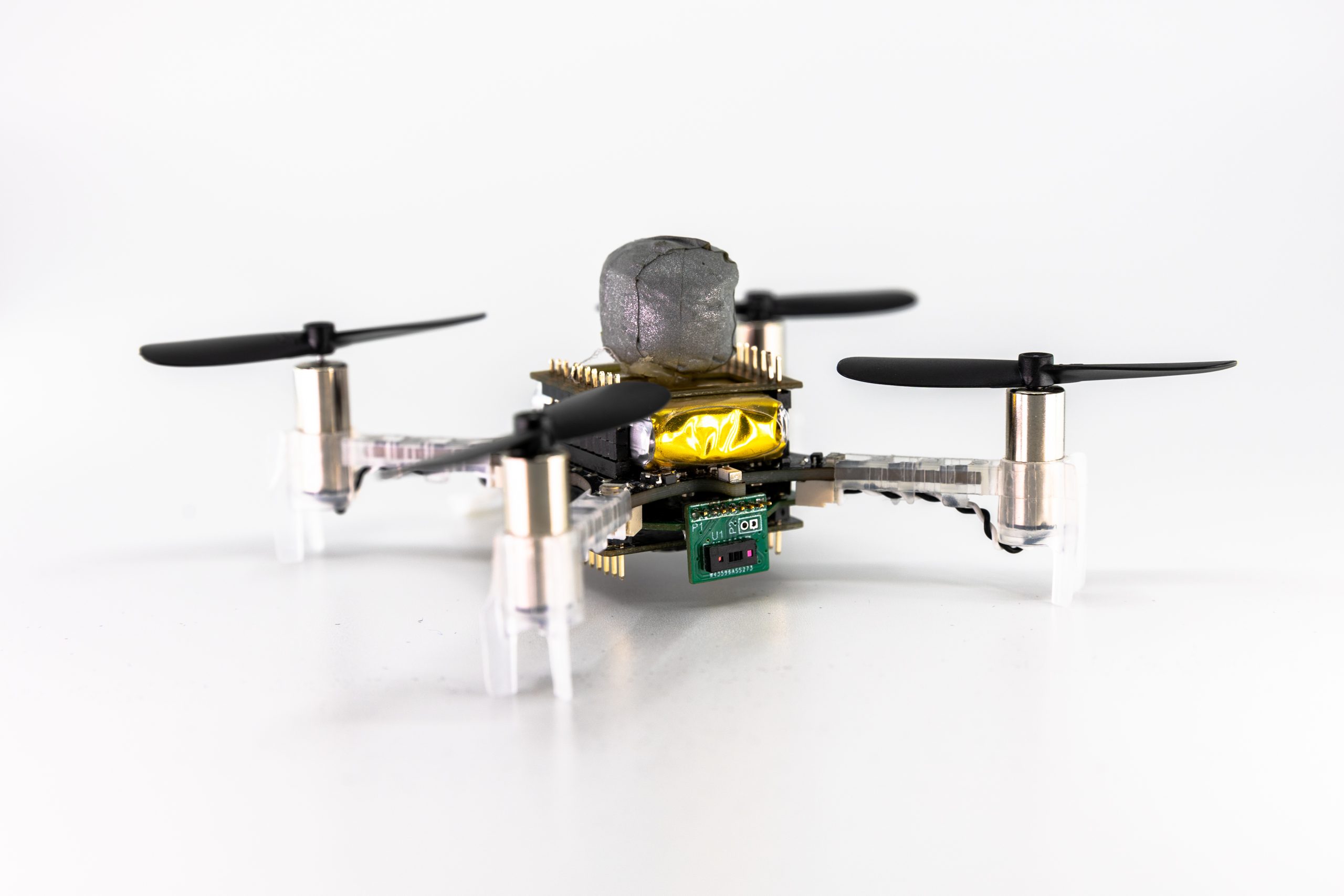
A Crazyflie 2.1 with our custom multi-zone ToF deck, a flow deck and a vicon marker.
Obstacle avoidance on nano-drones is challenging, as the restricted payload limits on-board sensors and computational power. Most approaches, therefore, use lightweight and ultra-low-power monocular cameras (as the AI-deck) or 1d depth sensors (as the multi-ranger deck). However, both those approaches have drawbacks – the camera images need extensive processing, usually even neural networks to detect obstacles. Neural networks additionally need training data and are prone to fail in completely new scenarios. The 1d depth sensors can reliably detect obstacles in their field of view (FoV); however, no information about the size or exact position of the obstacle is obtained.
On bigger drones, usually lidars or radars are used, but unfortunately, due to the limited weight and power consumption, those cannot be carried and used on nano-drones. However, in 2021 STMicroelectronics introduced a new multi-zone Time-of-Flight (ToF) sensor – with maximal 8×8 pixel resolution, a range up to 4m (according to the datasheet), a small form-factor and low power consumption of only 286mW (typical) it is ideal to use on nano-drones.
In the picture on top, you can see the Crazyflie 2.1 with our custom ToF deck (open-sourced at https://github.com/ETH-PBL/Matrix_ToF_Drones). We described this deck for the first time in [1], together with a sensor characterization. From this, we saw that we could use the sensor in different light conditions and on different colored obstacles, but from 2m on, the measurements started to get incomplete in all scenarios. However, as the sensor can detect invalid measurements (due to interference or obstacles being out of range), we can still rely on our information. In [2], we presented the system and some steps towards obstacle avoidance in a demo abstract, as you can see in the video below:
The next thing we did was to collect a dataset – we flew with different combinations of decks (flow-deck v2, AI-deck, our custom multi-zone ToF deck) and sometimes even tracked by a vicon system. Those recordings amount to an extensive dataset with depth images, RGB images, internal state estimation and the position and attitude ground truth.
We then fed the recorded data into a python simulation to develop an obstacle avoidance algorithm. We focused on only the ToF data (we are not fusing with the camera in this project, we just provide the data for future work). We aimed for a very efficient solution – because we want it to run on-board, on the STM32F405, with low latency and without occupying too many resources. Our algorithm is very lightweight but highly effective – we divide the FoV in different zones, according to how dangerous obstacles in those areas are and then use a decision tree to decide on a steering angle and velocity.
With only using up 0.31% of the computational power and 210 μs latency, we reached our goal of developing an efficient obstacle avoidance algorithm. Our system is also low-power, the power to lift the additional sensor with all accompanying electronics as well as the supply of it totals in less than 10% of the whole drone. On average, our system reaches a flight time of around 7 minutes. We refer to our preprint [3] for details on our various tests – they include flights with distances up to 212 m and 100% reliability and high agility at a low speed in an office environment.
As our paper is currently submitted but not yet accepted our code and dataset are not yet released – however, the hardware design is already accessible: https://github.com/ETH-PBL/Matrix_ToF_Drones
[1] V. Niculescu, H. Müller, I. Ostovar, T. Polonelli, M. Magno and L. Benini, “Towards a Multi-Pixel Time-of-Flight Indoor Navigation System for Nano-Drone Applications,” 2022 IEEE International Instrumentation and Measurement Technology Conference (I2MTC), 2022, pp. 1-6, doi: 10.1109/I2MTC48687.2022.9806701. [2] I. Ostovar, V. Niculescu, H. Müller, T. Polonelli, M. Magno and L. Benini, “Demo Abstract: Towards Reliable Obstacle Avoidance for Nano-UAVs,” 2022 21st ACM/IEEE International Conference on Information Processing in Sensor Networks (IPSN), 2022, pp. 501-502, doi: 10.1109/IPSN54338.2022.00051. [3] H.Müller, V. Niculescu, T. Polonelli, M. Magno and L. Benini “Robust and Efficient Depth-based Obstacle Avoidance for Autonomous Miniaturized UAVs”, submitted to IEEE, preprint: https://arxiv.org/abs/2208.12624
Before the summer vacations, I had the opportunity to spend some time working on AI deck improvements (blog post). One of the goals I set was to get CRTP over WiFi working, and try to fix issues along the way. The idea was to put together a small example where you could fly the Crazyflie using the keyboard and see the streamed image along the way. This would require both CRTP to the Crazyflie (logging and commands) as well as CPX to the GAP8 for the images. Just before heading off to vacation I managed to get the demo working, this post is about the results and som of the things that changed.
Link drivers
When using the Crazyflie Python library you connect to a Crazyflie using a URI. The first part of the URI (i.e radio or usb) selects what link driver to use for the connection. For example radio://0/80/2M/E7E7E7E7E7 selects the radio link driver, USB dongle 0 and communication at 2Mbit on channel E7E7E7E7E7.
While working on this demo there were two major things changed in the link drivers. The first one was the implementation of the serial link (serial://) which is now using CPX for CRTP to the Crazyflie. The usecase for this link driver is to connect a Raspberry Pi via a serial port to the Crazyflie on a larger platform.
The second change was to add a new link driver for connecting to the Crazyflie via TCP. Using this link driver it’s possible to connect to the Crazyflie via the network. It’s also possible to get the underlying protocol, the CPX object, for using CPX directly. This is used for communicating with for example the GAP8 to get images.
In the new TCP link driver the URI starts with tcp:// and has either an IP or a host name, followed by the port. Here’s two examples:
tcp://aideck-AABBCCDD.local:5000
tcp://196.168.0.100:5000
Comparison with the Crazyradio PA
So can WiFi be used now instead of the Crazyradio PA? Well, it depends. Using WiFi will give you larger throughput but you will trade this for latency. In our tests the latency is both larger and very random. In the demo I fly with the Flow V2 deck, which means latency isn’t that much of an issue. But if you were to fly without positioning and just use a joystick, this would not work out.
The Demo!
Below is a video of some flying at our office, to try it out yourself have a look at the example code here. Although the demo was mostly intended for improving CPX, we’ve made use of it at the office to collect training data for the AI deck.
The Crazyflie with AIdeck during over WiFI controlled flight.
Improvements
Unfortunately I was a bit short on time and the changes for mDNS discovery never made it it. Because of this there’s no way to “scan” or discover AI decks, so to connect you will need to know the IP or the host name. For now you can retrieve that by connecting to your AI-deck equipped Crazyflie with the CFclient and look at the console tab.
A part from that there’s more improvements to be made, with a better structure for using CPX (more like the CRTP stack with functions) in the library and more examples. There’s also still a few bugs to iron out, for example there’s still the improved FPS and WiFi throughput issues.
IMAV 2022
Next week from 13th to 16th of September Barbara, Kristoffer and Kimberly will be present at the international Micro Aerial Vehicle Conference and Competition (IMAV) hosted by the MAVlab of the TU Delft in the Netherlands. One of the competitions is called the nano quadcopter challenge, where teams will program a Crazyflie + AI deck combo to navigate through an obstacle field, so we are excited to see what solutions will come out of that. If any of you happens to be at the conference/competition, drop by our table to say hello!
you had probably seen me from the last blog post when I first arrived. I spent this summer working here in Malmö and I can definitely say that it was one great, educative and fun experience. During the last three months I have been in Bitcraze, I was given the chance to work and develop applications and demos on the robotics subject I am most interested in, drone collaboration.
Centralized Swarm with Multiple Flying Copter
I initially started looking into the implemented swarm demo which had 7 drones charging wirelessly in 7 charging decks and one of them flying by executing a spiral trajectory until it has a low battery and another one takes its place. The original swarm demo was shown at several conferences before the pandemic hit, but my plan was to improve it by adding more quadcopters flying simultaneously. The biggest problem was the collisions and ground effect happening between them. In order to solve that I was based on this paper and the optimization engine OpEn. I solved the problem of all drones starting from a point and going to a final one without colliding and covering the minimum distance by transferring these constraints into a cost function of an optimization problem assuming a simplified model for the quadcopter. Its output is waypoints for each quadcopter to pass from. These waypoints are transformed into a trajectory(piecewise polynomial) by a custom trajectory generator based on linear algebra.
In this way, I made it possible to execute non-colliding trajectories for 4 quadcopters, upload and execute them. While executing the first trajectory, the next one was being calculated and uploaded assuming the goal of the previous one as starting point. In this way, I managed to have 4 Crazyflies flying simultaneously and landing when their battery was running out and the fully charged ones were taking their place. This mechanism with some modifications can be used as a path planner or a standalone trajectory generator from a future user by feeding it waypoints and time durations for each waypoint segment. You can find the source code here.
Decentralized Swarm with Multiple Flying Copters
The aforementioned setup seemed to work pretty well but there was always the need of having a central PC monitoring and taking decisions for the whole swarm. So we wanted to move the architecture to a decentralized one, of which Kristoffer did some preliminary work shown at BAMdays last year. This was made possible by utilizing the onboard peer-to-peer protocol (P2P) in collaboration with the onboard collision avoidance algorithm introduced in this PR contributed by James Preiss from the University of Southern California. All the Crazyflies share their position and state through the protocol by broadcasting them at a rate of 15 Hz.
Although there were some missed packets, they could avoid each other while flying by updating the collision avoidance algorithm which is taking action between the high level and the action commander by altering its waypoints. The decisions of which drone should take off or land are also taken in a decentralized way. Whenever one copter is about to take off it enters the corresponding state and assigns itself a randomized timeout. During this timeout, if the desired number of airborne copters is achieved it goes back to idle. If not and the timeout occurs it finally take-offs. So, despite there is not an actual common decision, the swarm can be led to simple desired states like keeping the number of the drones flying constant and executing changes between the landed, charged copters and flying ones. You can find the source code here.
Token Ring Implementation
After I finished this project and since I had some extra time left I decided to work more in the P2P protocol. The need for having a robust way to communicate between the Crazyflies and a way to verify that a packet was indeed sent was obvious. A solution to this problem was offered by Christos Zosimidis and Klaus Kefferpütz from the Cooperative Control Lab in Hochschule Augsburg, namely a token ring implementation. I would really like to thank them for this collaboration and hope for future ones as well.
Specifically, the proposed token ring protocol was implemented in a modified version of the nrf-radio firmware and the Crazyradio. This protocol assumes that each Crazyflie is a node of a network and a token is passed around giving permission to each drone that has it in its possession to broadcast data. So, each time only one Crazyflie broadcasts data which leads to fewer packet collisions and losses. It can also acknowledge that a node has received the data targeting to it and then continues to others. The interface with the protocol is being done by 2 queues (TX and RX) where the user can place data that wants to send and read the RX queue to receive. The moment that this blog post is being written only the static version of it is public in the firmware, which means that the number and the id of the Crazyflies must be defined before execution and in case a copter fails the whole network fails. Although, I am currently working on a dynamic approach that is going to solve these problems
All in all, I had a great time here in Malmo despite the fact that the Swedish summer is much colder than the warm weather I was used to in Greece. I was amazed by the way things in Bitcraze work and how the whole company operates. It was a pleasure being around so creative people and I am happy that I could help even in a small way. Thank you very much for giving me the opportunity to work with you and I hope I will keep on contributing to this amazing project in the future.
After a period of bitcrazer-vacations, we are now all back at work. The summer here in Sweden has generally been great. Some of us stayed here to keep the company afloat, and some just stayed afloat on lakes or the sea. The majority vacationed inside of Sweden, but some (could you guess who?) have visited France, Italy, or Greece. We’ve been lucky with a mostly warm and sunny weather, perfect for bathing and grilling. And even though it’s nice to enjoy real summer, it’s still worrying sign though, as Europe is experiencing what could be the worst drought in 500 years.
Crazyflie 2.1 back in stock
What is also back is the Crazyflie 2.1, but back in stock, yay! After almost two weeks without any drones available for sale, we received a new batch of our quadcopter today. It should now be available in the shop, just in time for when school starts!
We got some indications the component shortage are slowly moving in the right direction so hopefully it will get easier to keep things in stock in the future. We are keeping our fingers crossed.
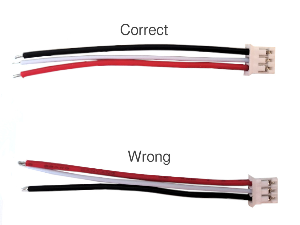
Bolt 1.1 ESC cable red/black switched
Unfortunately we recently found out that there has been a manufacturing error with the ESC cables that come with the Bolt 1.1. The black and red cables have been switched. Please see the image below.
With the black and red cables switched this will result in powering your ESCs with reversed polarity. This will most likely burn the MOSFET on the Bolt that controls the power to the ESC, which is the weakest link. This because the MOSFET body diodes on the ESC will conduct and make the whole ESC a short circuit. In many setups, e.g using 4in1 ESC these cables are not used though and will not cause a problem.
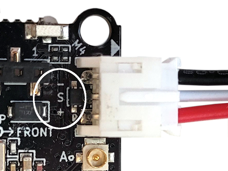
Switching the cables back is quite easy to do. Use a needle, tweezer or e.g. small screwdriver to open the plastic lock so the cable can be pulled out. Switch the black and red and you are done. You can double check that the colors are correct by comparing it with the Bolt 1.1 board. The plus and minus should match with the red and black as per the image below:
We are currently working with the manufacturer to get correct cables. If you got a Bolt 1.1 (anytime between June and August 2022) we can of course ship you correct cables once they are ready or give you support if you got problems with the control board. If so, please send us an email to support@bitcraze.io. Sorry for this inconvenience!
There are some nice and exciting improvement in the CF-client that we worked on during the summer months! First of all we worked on a toolbox structure, where every tab can be reconfigured as a toolbox as well, allowing it to be docked to the sides of the window. Secondly we have added a new geometry estimation wizard for Lighthouse systems to support multi base-station estimation. Finally we have added a new tab for PID controller tuning, mainly intended for the Bolt.
New tabs, toolboxes and wizards for the CFclient
Toolboxes in the CFclient
Everyone who used the CFclient has experienced the tabs before. Anytime you want to configure the lighthouse system, setup plotting or look at the parameter states, you switch to the appropriate tab to perform your desired action. This is all fine, but sometimes it can be useful to see the contents of two tabs at the same time, maybe you want to watch the graphing of a log variable at the same time as you change a parameter. This is what the combined tab/toolbox feature adds! Any tab can now be converted into a toolbox that can be docked to the side of the window.
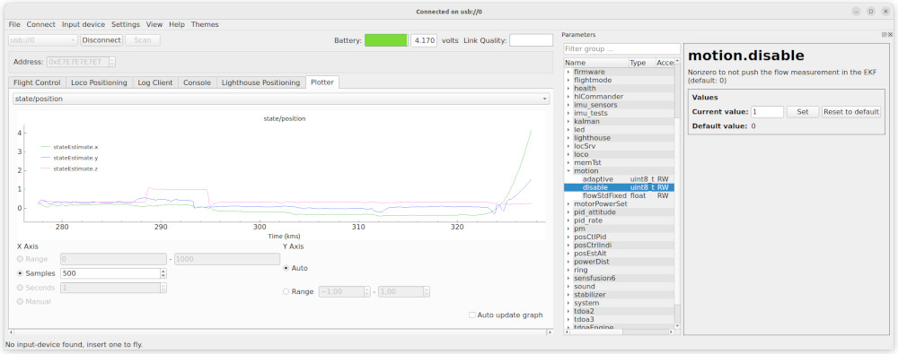
Plotter tab with parameter toolbox
In the example above the plotter is displaying the estimated position of a Crazyflie with a Flow deck, while the parameter window is opened as a toolbox. The “motion.disable” parameter was just set to true and we can see that the kalman estimator gets into trouble when it no longer gets data from the flow deck.
To switch from tab to toolbox mode, go to the View/Toolboxes menu and select the window that you want to show as a toolbox. In a similar way, use the View/Tabs menu to turn it back to a tab.
Even though all tabs can be turned into toolboxes, some of them might still look better as tabs due to their design. We hope to be able to improve the design over time and make them more toolbox friendly, contributions are welcome!
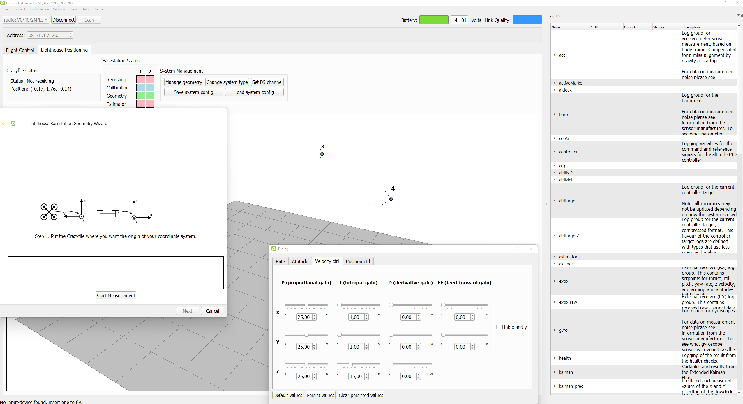
Lighthouse Geometry Estimation Wizard
In a blogpost of almost a half year ago, we presented a new multi base station geometry estimation method that enabled the user to include more than 2 base station for flying a Crazyflie. This heavily increases the flight area covered by the base station V2s, as technically it should be able to handle up to 16!
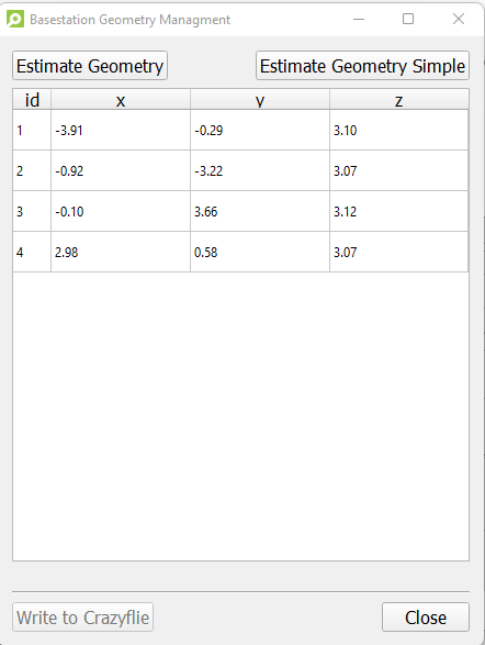
New geometry estimation dialog
However, up until this summer it has been in experimental mode as we weren’t so sure as how stable this new estimation method is, so the only way to use it was via a script in the Crazyflie python library directly, and not from the CFclient. Since we haven’t heard of anybody having problems with this new experimental feature, we decided to go ahead to make a nice multi base station geometry estimation wizard in the CFclient’s Lighthouse tab.
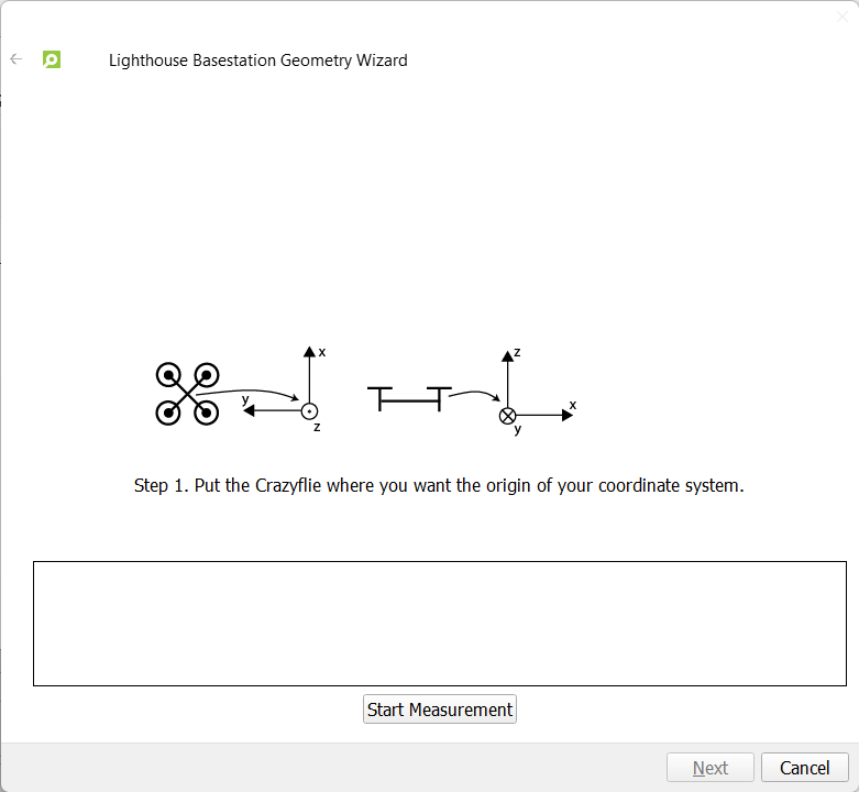
This wizard can be accessed if you go to the lighthouse tab-> ‘manage geometry’ and press ‘Estimate Geometry’. We had to make it a wizard as this new method requires some extra intermediate steps compared to the previous, to ensure proper scaling, ground plane setting and sweep angle recording. If you are only using 2 base stations this seems like extra effort, where you only had to put the Crazyflie on the ground and push a button, but if you compare flight performance of the two methods, you will see an immediate difference in positioning quality, especially around the edges of your flight area. So it is definitely worth it!
First page of the wizard
We will still provide the “simple” option for those that want to use it, or want to geometry estimate only one base-station, as we don’t have support for that for this new estimator (see this issue). In that case, you will have to install the headless version of opencv separately like ‘pip3 install opencv-python-headless’. We will remove this requirement from the cflib itself for the next release as there are conflicts for users who has installed the non-headless opencv on their system, like for the opencv-viewer of the AI-deck’s wifi streamer for instance.
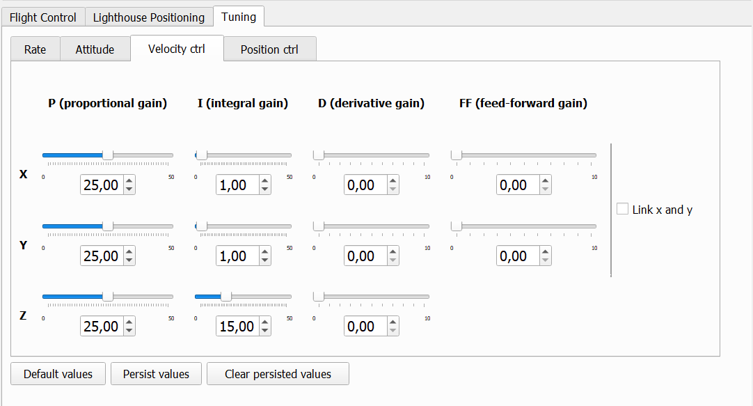
PID tuning tab
The PID controller tuning tab
And last but not least, we introduced an PID tuning tab in a PR in the CFClient! And of course… also available as a toolbox :) This is maybe not super necessary for the Crazyflie itself, but for anyone working with a custom frame with the Bolt or BigQuad deck this is quite useful. Tuning is much handier with a slider than to adjust each parameter numerically with the parameter tab. Also if you are just interested of what would happen if you would increase the proportional gain of the z-position controller of the crazyflie, this would be fun to try as well… but of course at your own risk!
If you are happy with your tuned PID values, there is the “Persist Values” button which will store the parameters in the EEPROM memory of the Crazyflie/Bolt, which means that these values will persist even after restarting the platform. This can be cleared with the ‘Clear persisted values’ button and you can retrieve the original firmware-hardcoded default values with ‘Default Values’ button. Please check out this blogpost to learn more about persistent parameters.
Try it out for yourself!
This client has not been released yet but you can already go ahead and try these new features out for yourself. Make sure to first install the client from source, and then install the CFlib from source, as an update of both is necessary. Also update the crazyflie-firmware to the latest development branch via these instructions, especially if you want to try out the new LH geometry wizard.
And of course, don’t forget to give us feedback on discussions.bitcraze.io or to make an issue on the cfclient, cflib or crazyflie-firmware github repositories if you are hitting a bug on your machine and you know pretty precisely where it comes from.
Unmanned Aerial Vehicles (UAVs) have garnered much attention from both researchers and engineers in recent decades. Aerial robots in general are classified into mainly three categories: fixed wings, rotary wings and flapping wings.
Fixed wings are one of the most common aerial vehicles as it has relatively higher power efficiency and payload capacity than other types, thanks to their big and highly customizable wing. But this also leads to a bigger footprint and usually the lack of ability for Vertical Taking Off and Landing (VTOL). Rotary wings generally include helicopter and multirotors (such as quadrotors), and they have recently become increasingly popular in our daily lives. Easily achieving great performance in attitude and position control, rotary wings are widely applied in many fields. Flapping wing robots take inspirations from small flapping insects (such as Harvard Robobee) or birds (Purdue Hummingbird Robot).
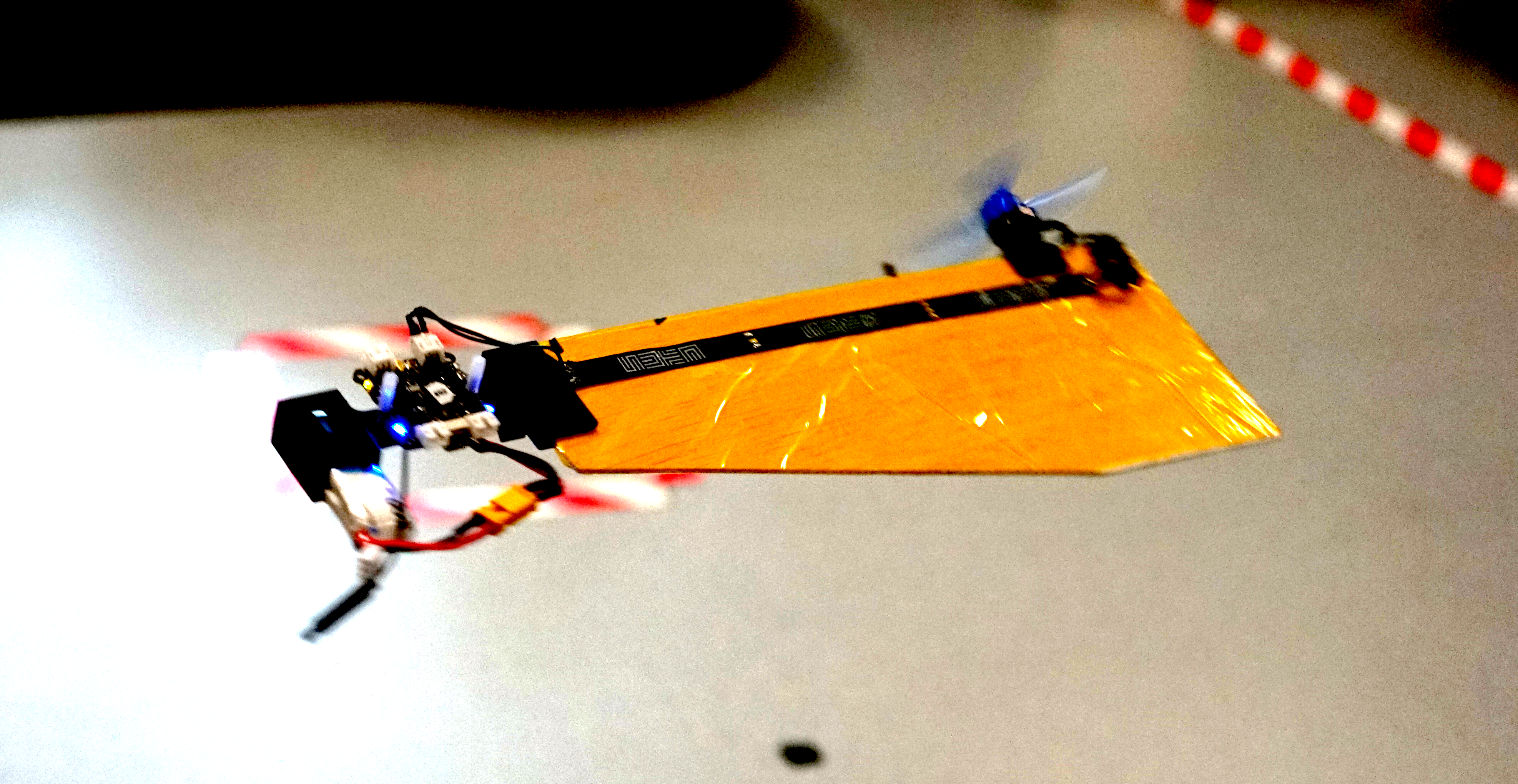
Fig: A simple prototype of SAM from SUTD with Crazyflie Bolt.
Monocopters are largely inspired from the falling motion of maple seeds, and they are relatively much simpler to build as compared to its counterparts. They can keep a relative smaller footprint and achieve decent control performance although they are highly underactuated. The Single Actuator Monocopter (SAM) has the ability to VTOL, perform 3D trajectory tracking as well as maintain high hovering efficiency. With those advantages, rapid developments have been made in recent years such as the Foldable Single Actuator Monocopter (F-SAM) and Modular Single Actuator Monocopter (M-SAM) from Engineering Product Development (EPD) of Singapore University of Technology and Design (SUTD).
Taking inspiration from nature – Samara inspired monocopter
A descending samara or maple seed, is able to passively enter auto-rotation motion and stabilize its flight attitude, helping to slow down its descent speed and travel further for better survival of the species. This natural behavior attracts interests from scientists and researchers. With previous studies, we learnt that this passive attitude stability is mainly guaranteed by mass distribution (Center of Mass) and wing geometry (Center of Pressure) as well as the rotation motion.
A maple seed inspired Single Actuator Monocopter (SAM).
The SAM is designed to be very close in its mechanical make-up to its natural sibling, having a large single wing structure and a smaller, denser ‘seed’ structure. A single motor with propeller is installed on the leading edge, parallel to the wing surface. Comparing with flight dynamics of the original maple seed, SAM has extra torques and force caused by the spinning propeller, including a reaction torque and thrust directly from propeller, as well as an extra torque caused by precession motion. As a result, the balance of the combined forces and torques allows SAM to enter a new equilibrium condition while still retaining the passive attitude stability.
Development of monocopters
The research on monocopters can be traced back to a long time ago. Here are some examples of different types of air frame to roughly introduce their developments. An air-frame called Robotic Samara [1] was created in 2010, which has a motor to provide rotational force, a servo to control collective pitch of the wing, a winged body fabricated by carbon fiber, and a lipo battery. In the following year, Samarai MAV [2] was developed by following the mass distribution of a natural maple seed. To achieve the control, a servo is equipped to regulate the wing flap. In 2020, a single actuator monocopter was introduced with a simplified air-frame [3]. The main structure is made by laminated balsa wood while the trailing edge of the wing is made by foam for better mass distribution. By making use of the passive attitude stability, only one actuator is required to control the position in 3D space. Based on which, F-SAM [4] and M-SAM [5] were developed in 2021 and 2022 respectively.
SAM with foldable wing structure (F-SAM).
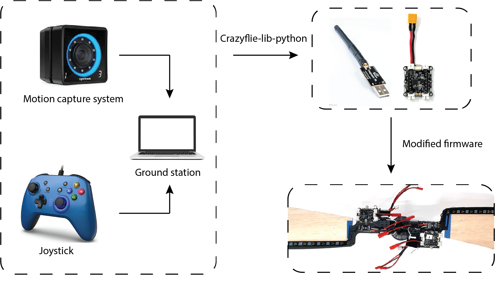
A Modular SAM (M-SAM) with Crazyflie Bolt
Thanks to its easy implementation and reliable performance, we use the Crazyflie Bolt as the flight controller for M-SAM. Like other robotic systems, the ground station is integrated with motion capture system (position and attitude feedback for both control and ground truth) and a joystick (control reference directly generated by user) is responsible for sending filtered state feedbacks and control references or control signal directly to flight controller. This is realized by employing the Crazyradio PA under the Crazyflie-lib-python environment. Simple modifications from the original firmware were made to map from the control reference to motor command (a customized flight controller).
A diagram shows how Crazyflie Bolts work in M-SAM project.
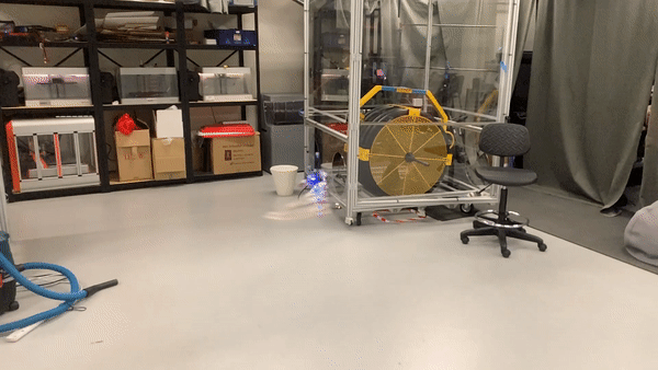
Another advantage of using Crazyflie Bolt in M-SAM project is its open source swarm library. Under the swarm environment, SAMs can fly in both singular and cooperative configurations. With simple human assistance, two SAMs can be assembled into cooperative configuration by making use of a pair of magnetic connectors. The mid-air separation from cooperative configuration to singular configuration is passively triggered by increasing the rotating speed until the centrifugal force overcomes the magnetic force.
Modular Single Actuator Monocopters (M-SAM), which is able to fly in both singular and cooperative configuration.
Potential applications
What kinds of applications can be achieved with the monocopter aerial robotic platform? On the one hand, many applications are limited by the nature of self-rotation motion. On the other hand, the passive rotating body also offers advantages in some special scenarios. For example, SAM is an ideal platform for LIDAR application, which usually requires the rotating motion to sense the environment around. Besides, thanks to simple mechanical design and cheap manufacturing cost, SAM can be designed for one time use such as light weight air deployment or unknown, dangerous environments.
An example [6] shows the potential applications of a rotating robot with camera.
Reference
[1] Ulrich, Evan R., Darryll J. Pines, and J. Sean Humbert. “From falling to flying: the path to powered flight of a robotic samara nano air vehicle.” Bioinspiration & biomimetics 5, no. 4 (2010): 045009.
[2] Fregene, Kingsley, David Sharp, Cortney Bolden, Jennifer King, Craig Stoneking, and Steve Jameson. “Autonomous guidance and control of a biomimetic single-wing MAV.” In AUVSI Unmanned Systems Conference, pp. 1-12. Arlington, VA: Assoc. for Unmanned Vehicle Systems International, 2011.
[3] Win, Luke Soe Thura, Shane Kyi Hla Win, Danial Sufiyan, Gim Song Soh, and Shaohui Foong. “Achieving efficient controlled flight with a single actuator.” In 2020 IEEE/ASME International Conference on Advanced Intelligent Mechatronics (AIM), pp. 1625-1631. IEEE, 2020.
[4] Win, Shane Kyi Hla, Luke Soe Thura Win, Danial Sufiyan, and Shaohui Foong. “Design and control of the first foldable single-actuator rotary wing micro aerial vehicle.” Bioinspiration & Biomimetics 16, no. 6 (2021): 066019.
[5] X. Cai, S. K. H. Win, L. S. T. Win, D. Sufiyan and S. Foong, “Cooperative Modular Single Actuator Monocopters Capable of Controlled Passive Separation,” 2022 International Conference on Robotics and Automation (ICRA), 2022, pp. 1989-1995, doi: 10.1109/ICRA46639.2022.9812182.
[6] Bai, Songnan, Qingning He, and Pakpong Chirarattananon. “A bioinspired revolving-wing drone with passive attitude stability and efficient hovering flight.” Science Robotics 7, no. 66 (2022): eabg5913.
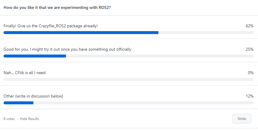
Now it is time to give a little update about the ongoing ROS2 related projects. About a month ago we gave you an heads-up about the Summer ROS2 project I was working on, and even though the end goal hasn’t been reached yet, enough has happened in the mean time to write a blogpost about it!
Crazyflie Navigation
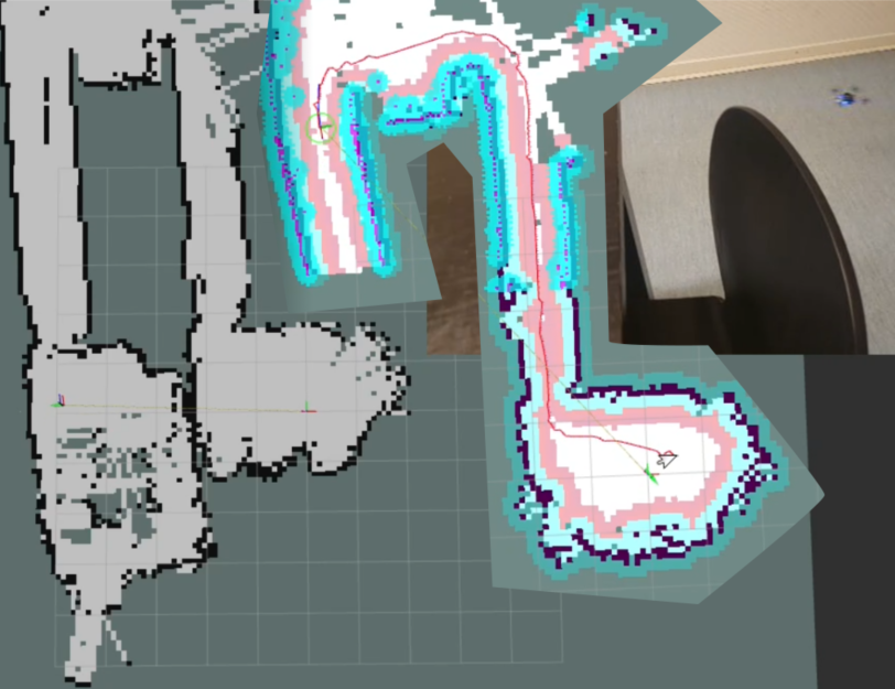
Last time showed mostly mapping of a single room, so currently I’m trying to map a bigger portion of the office. This was initially more difficult then initially anticipated, since it worked quite well in simulation, but in real life the multi-ranger deck saw obstacles that weren’t there. Later we found out that was due to this year old issue of the multi-ranger’s driver incapability to handle out-of-range measurements properly (see this ongoing PR). With that, larger scale mapping starts to become possible, which you can see here with the simple mapper node:
If you look at the video until the end, you can notice that the map starts to diverge a bit since the position + orientation is solely based on the flow deck and gyroscopes , which is a big reason to get the SLAM toolbox to work with the multi-ranger. However, it is difficult to combine it with such a sparse ‘Lidar’ , so while that still requires some tuning, I’ve taken this opportunity to see how far I get with the non-slam mapping and the NAV2 package!
As you see from the video, the Crazyflie until the second hallway. Afterwards it was commanded to fly back based on a NAV2 waypoint in RViz2. In the beginning it seemed to do quite well, but around the door of the last room, the Crazyflie got into a bit of trouble. The doorway entrance is already as small as it is, and around that moment is also when the mapping started to diverge, the new map covered the old map, blocking the original pathway back into the room. But still, it came pretty close!
The diverging of the map is currently the blocker for larger office navigation, so it would be nice to get some better localization to work so that the map is not constantly changed due to the divergence of position estimates, but I’m pretty hopeful I’ll be able to figure that out in the next few weeks.
Crazyflie ROS2 node with CrazySwarm2
Based on the poll we set out in the last blogpost, it seemed that many of you were mostly positive for work towards a ROS2 node for the Crazyflie! As some of you know, the Crazyswarm project, that many of you already use for your research, is currently being ported to ROS2 with efforts of Wolfgang Hönig’s IMRCLab with the Crazyswarm2 project. Instead of in parallel creating separate ROS2 nodes and just to add to the confusion for the community, we have decided with Wolfgang to place all of the ROS2 related development into Crazyswarm2. The name of the project will be the same out of historical reasons, but since this is meant to be the standard Crazyflie ROS2 package, the names of each nodes will be more generic upon official release in the future.
To this end, we’ve pushed a cflib python version of the crazyflie ros2 node called crazyflie_server_py, a bit based on my hackish efforts of the crazyflie_ros2_experimental version, such that the users will have a choice of which communication backend to use for the Crazyflie. For now the node simply creates services for each individual Crazyflie and the entire swarm for take_off, land and go_to commands. Next up are logging and parameter handling, positioning support and broadcasting implementation for the CFlib, so please keep an eye on this ticket to see the process.
So hopefully, once the summer project has been completed, I can start porting the navigation capabilities into the the Crazyswarm2 repository with a nice tutorial :)
ROScon talk
As mentioned in a previous blogpost, we’ll actually be talking about the Crazyflie ROS2 efforts at ROScon 2022 in Kyoto in collaboration with Wolfgang. You can find the talk here in the ROScon program, so hopefully I’ll see you at the talk or the week after at IROS!
Advancements in technology have made quadrotor drones more accessible and easy to integrate into a wide variety of applications. Compared to traditional fixed-wing aircraft, quadrotors are more flexible to design and more suitable for motioning, such as statically hovering. Some examples of quadrotor applications include photographers using mounting cameras to take bird’s eye view images, and delivery companies using them to deliver packages. However, while being more versatile than other aerial platforms, quadrotors are still limited in their capability due to many factors.
First, quadrotors are limited by their lift capacity, i.e., strength. For example, a Crazyflie 2.1 is able to fly and carry a light payload such as an AI deck, but it is unable to carry a GoPro camera. A lifter quadrotor that is equipped with more powerful components can transport heavier payload but also consumes more energy and requires additional free space to operate. The difference in the strength of individual quadrotors creates a dilemma in choosing which drone components are better suited for a task.
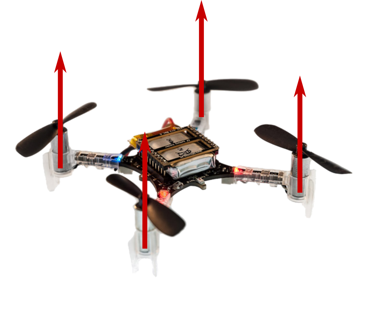
Second, a traditional quadrotor’s motion in translation is coupled with its roll and pitch. Let’s take a closer look at Crazyflie 2.1, which utilizes a traditional quadrotor design. Its four motors are oriented in the same direction – along the positive z-axis of the drone frame, which makes it impossible to move horizontally without tilting. While such control policies that convert the desired motion direction into tilting angles are well studied, proven to work, and implemented on a variety of platforms [1][2], if, for instance, we want to stack a glass filled with milk on top of a quadrotor and send it from the kitchen to the bedroom, we should still expect milk stains on the floor. This lack of independent control for rotation and translation is another primary reason why multi-rotor drones lack versatility.
These versatility problems are caused by the hardware of a multi-rotor drone designed specifically to deal with a certain set of tasks. If we push the boundary of these preset tasks, the requirements on the strength and controllability of the multi-rotor drone will eventually be impossible to satisfy. However, there is one inspiration we take from nature to improve the versatility in the strength of multi-rotor drones – modularity! Ants are weak individual insects that are not versatile enough to deal with complex tasks. However, when a group of ants needs to cross natural boundaries, they will swarm together to build capable structures like bridges and boats. In our previous work, ModQuad [3], we created modules that can fly by themselves and lift light payloads. As more ModQuad modules assemble together into larger structures, they can provide an increasing amount of lift force. The system shows that we can combine weak modules with improving the versatility of the structure’s carrying weight. To carry a small payload like a pin-hole camera, a single module is able to accomplish the task. If we want to lift a heavier object, we only need to assemble multiple modules together up to the required lift.
Improving controllability
On a traditional quadrotor, each propeller is oriented vertically. This means the device is unable to generate force in the horizontal direction. By attaching modules side by side in a ModQuad structure, we are aligning more rotors in parallel, which still does not contribute to the horizontal force the structure can generate. That is how we came up with the idea of H-ModQuad — we would like to have a versatile multi-rotor drone that is able to move in an arbitrary direction at an arbitrary attitude. By tilting the rotors of quadrotor modules and docking different types of modules together, we obtain a structure whose rotors are not pointing in the same direction, some of which are able to generate a force along the horizontal direction.
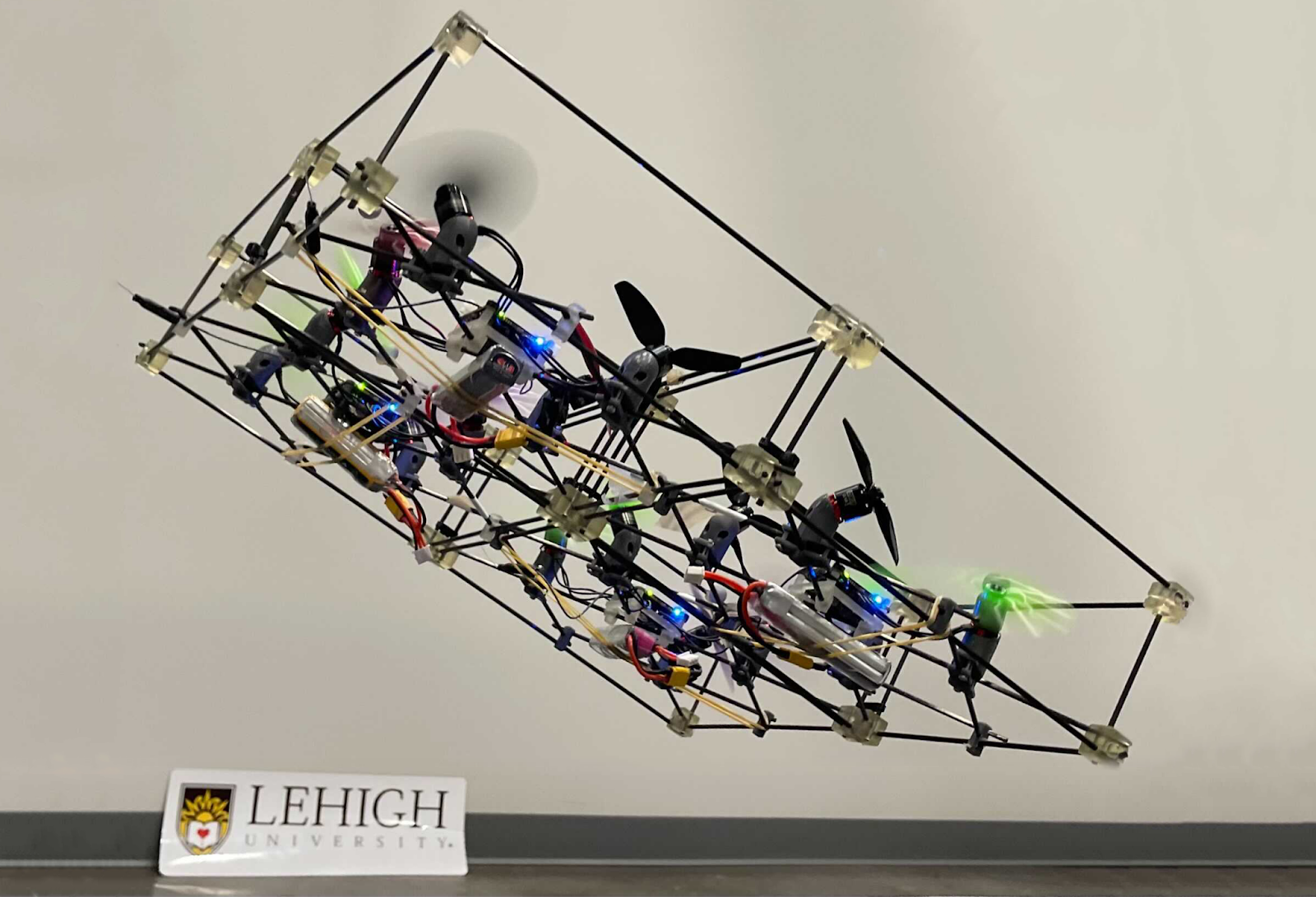
H-ModQuad Design
H-ModQuad has two major characteristics: modularity and heterogeneity, which can be indicated by the “Mod” and “H-” in the name. Modularity means that the vehicle (we call a structure) is composed of multiple smaller modules which are able to fly by themselves. Heterogeneity means that we can have modules of different types in a structure.
As mentioned before, insects like ants utilize modularity to enhance the group’s versatility. Aside from a large number of individuals in a swarm that can adapt to the different scales of the task requirement, the individuals in a colony specializing in different tasks are of different types, such as the queen, the female workers, and the males. The differentiation of the types in a hive helps the group adapt to tasks of different physical properties. We take this inspiration to develop two types of modules.
In our related papers [4][5], we introduced two types of modules which are R-modules and T-modules.
Fig 2. Major components of an H-ModQuad “T-module” we are using in our project. We use Bitcraze Crazyflie Bolt as the central control board.
An example T-module is shown in the figure above. As shown in the image, the rotors in a T-module are tilted around its arm connected with the central board. Each pair of diagonal rotors are tilted in the opposite direction, and each pair of adjacent rotors are either tilting in the same direction or in the opposite direction. We arrange the tilting of the rotors so that all the propellers generate the same thrust force, making the structure torque-balanced. The advantage of the T-module is that it allows the generation of more torque around the vertical axis. One single module can also generate forces in all horizontal directions.
An R-module has all its propellers oriented in the same direction that is not on the z-axis of the module. In this configuration, when assembling multiple modules together, rotors from different modules will point in different directions in the overall structure. The picture below shows a fully-actuated structure composed of R-modules. The advantage of R-modules is that the rotor thrusts inside a module are all in the same direction, which is more efficient when hovering.
Structure 1: Composed of four types of R-modules.
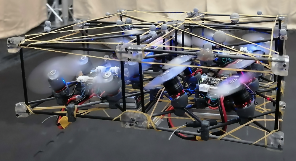
Depending on what types of modules we choose and how we arrange those modules, the assembled structure can obtain different actuation capabilities. Structure 1 is composed of four R-modules, which is able to translate in horizontal directions efficiently without tilting. The picture in the intro shows a structure composed of four T-modules of two types. It can hover while maintaining a tilting angle of up to 40 degrees.
Control and implementation
We implemented our new geometric controller for H-ModQuad structures based on Crazyflie Firmware on Crazyflie Bolt control boards. Specifically, aside from tuning the PID parameters, we have to change the power_distribution.c and controller_mellinger.c so that the code conforms to the structure model. In addition, we create a new module that embeds the desired states along predefined trajectories in the firmware. When we send a timestamp to a selected trajectory, the module retrieves and then sends the full desired state to the Mellinger Controller to process. All modifications we make on the firmware so that the drone works the way we want can be found at our github repository. We also recommend using the modified crazyflie_ros to establish communication between the base station and the drone.
Videos
Challenges and Conclusion
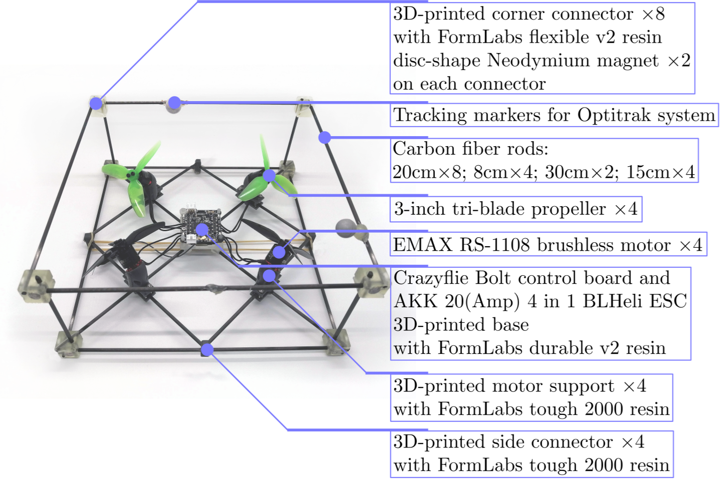
Different from the original Crazyflie 2.x, Bolt allows the usage of brushless motors, which are much more powerful. We had to design a frame using carbon fiber rods and 3-D printed connecting parts so that the chassis is sturdy enough to hold the control board, the ESC, and the motors. It takes some time to find the sweet spot of the combination of the motor model, propeller size, batteries, and so on. Communicating with four modules at the same time is also causing some problems for us. The now-archived ROS library, crazyflie_ros, sometimes loses random packages when working with multiple Crazyflie drones, leading to the stuttering behavior of the structure in flight. That is one of the reasons why we decided to migrate our code base to the new Crazyswarm library instead. The success of our design, implementation, and experiments with the H-ModQuads is proof of work that we are indeed able to use modularity to improve the versatility of multi-rotor flying vehicles. For the next step, we are planning to integrate tool modules into the H-ModQuads to show how we can further increase the versatility of the drones such that they can deal with real-world tasks.
Reference
[1] D. Mellinger and V. Kumar, “Minimum snap trajectory generation and control for quadrotors,” in 2011 IEEE International Conference on Robotics and Automation, 2011, pp. 2520–2525.
[2] T. Lee, M. Leok, and N. H. McClamroch, “Geometric tracking control of a quadrotor uav on se(3),” in 49th IEEE Conference on Decision and Control (CDC), 2010, pp. 5420–5425.
[3] D. Saldaña, B. Gabrich, G. Li, M. Yim and V. Kumar, “ModQuad: The Flying Modular Structure that Self-Assembles in Midair,” 2018 IEEE International Conference on Robotics and Automation (ICRA), 2018, pp. 691-698, doi: 10.1109/ICRA.2018.8461014.
[4] J. Xu, D. S. D’Antonio, and D. Saldaña, “Modular multi-rotors: From quadrotors to fully-actuated aerial vehicles,” arXiv preprint arXiv:2202.00788, 2022.
[5] J. Xu, D. S. D’Antonio and D. Saldaña, “H-ModQuad: Modular Multi-Rotors with 4, 5, and 6 Controllable DOF,” 2021 IEEE International Conference on Robotics and Automation (ICRA), 2021, pp. 190-196, doi: 10.1109/ICRA48506.2021.9561016.
We’re now in the middle of summer, and even though we’re not affected by the heat much here in Sweden, we’re still in a slower pace as usual, since a lot of us are not at the office. Sales, packing, support and general maintenance takes up a lot of our time for those that are left at the office. We also usually take the summer time to clear out lingering issues and focus on some projects that we can tackle alone.
This summer though will be mostly used for preparation of a very busy autumn. As the Covid situation seems to normalize around the world, conferences onsite are restarting, and we plan to take advantage of this ! Here is what is planned:
IMAV – Delft, 12 to 16 September.
The 13th edition of the International Micro Air Vehicle Conference will be held in Delft, in the Netherlands. We’ve been collaborating for a long time with the MAVLab in Delft, so we’re really happy to be one of the sponsors for this conference. For the occasion, there is a nano AI competition that we’re really excited to see. With the AI bundle, the goal is to fly as fast as possible through an obstacle course.
We’ve been working a lot with the AI deck this past year, so this competition is the perfect occasion for us to see it in action. Kimberly has also developed a simulator that will be used for this competition.
ROSCon – Kyoto, 19 to 21 october
ROSCon is a conference dedicated to the entire ROS community, traditionally held right before IROS. Kimberly will be our proud represent there, as she will have a talk about ROS2 and the Crazyflie. For the occasion, she will showcase the latest ROS2 integrations in collaboration with the maintainers of Crazyswarm2.
Last time a Crazyflie was present at ROSCon was in 2015, where Wolfgang Hönig had a lightning talk. A lot has changed since that time, and we’re hoping to increase the presence of (tiny) aerial vehicles within the ROS community, especially nanocopters like the Crazyflie.
IROS – Kyoto, 23 to 27 october
IROS is one of the largest robotics conferences worldwide, and after an online edition last year, this 35th instance promises to be full of exciting things!
As it’s quite huge, and for a quite delayed 10th Bitcraze’s anniversary, the whole company plans to get to this conference. Not only for the chance to discover Japan, that most of us haven’t visited, but also because it feels important to have a significant presence in this conference, which promises a lot of opportunities. That would mean a week without anyone at the Swedish office, but you know where to find us if you would like to talk to us ;).
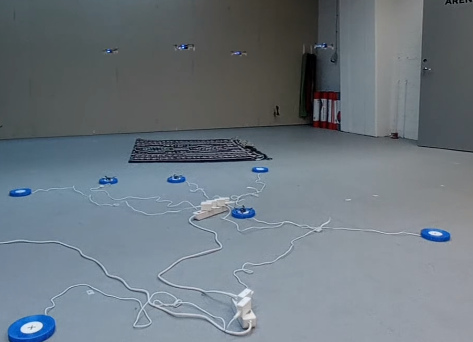
For the occasion, our intern Marios is working on revamping the autonomous swarm demo. Because of the pandemic, it’s been a while since we actually used it for a whole day of flying, and he’s actively working on making it completely autonomous by implementing the peer to peer protocol.
Logistics
As you can see, those exciting 3 conferences almost back-to-back promise a busy autumn here at Bitcraze. There’s a lot to prepare ahead of time, like marketing materials, demo setups, visas problems and hotel bookings. And there will be a lot to talk about, during and after. The pandemics have delayed a lot of our in-person meetings, and it will feel really good to finally get to meet up in the real world with users – old and new. If you have the opportunity, don’t hesitate to come by our booths on those conferences and say hello in person!