Christmas is just around the corner, and it’s time for the traditionnal Christmas video! This year, we wanted to use the AI deck as we’ve been working hard on this deck for some time now. Showcasing its new feature in this festive video seemed the best idea.
Santa this year needed help to find and get the presents delivered, so he asked for help from Bitcraze! Let’s see how it played out:
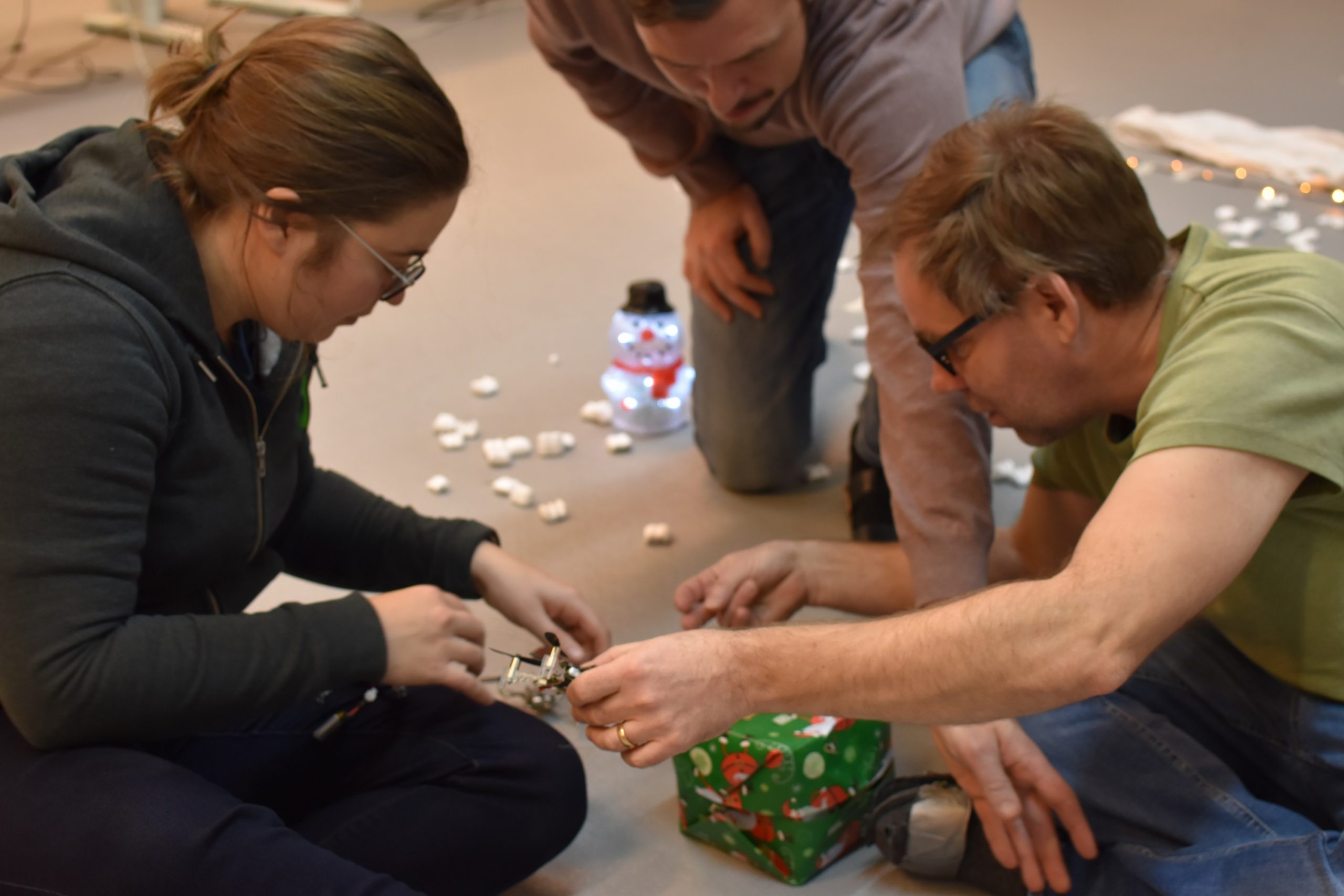
I’m sure you’re wondering how we managed to set this up, so let’s discuss how we did it!
Picking up the packages
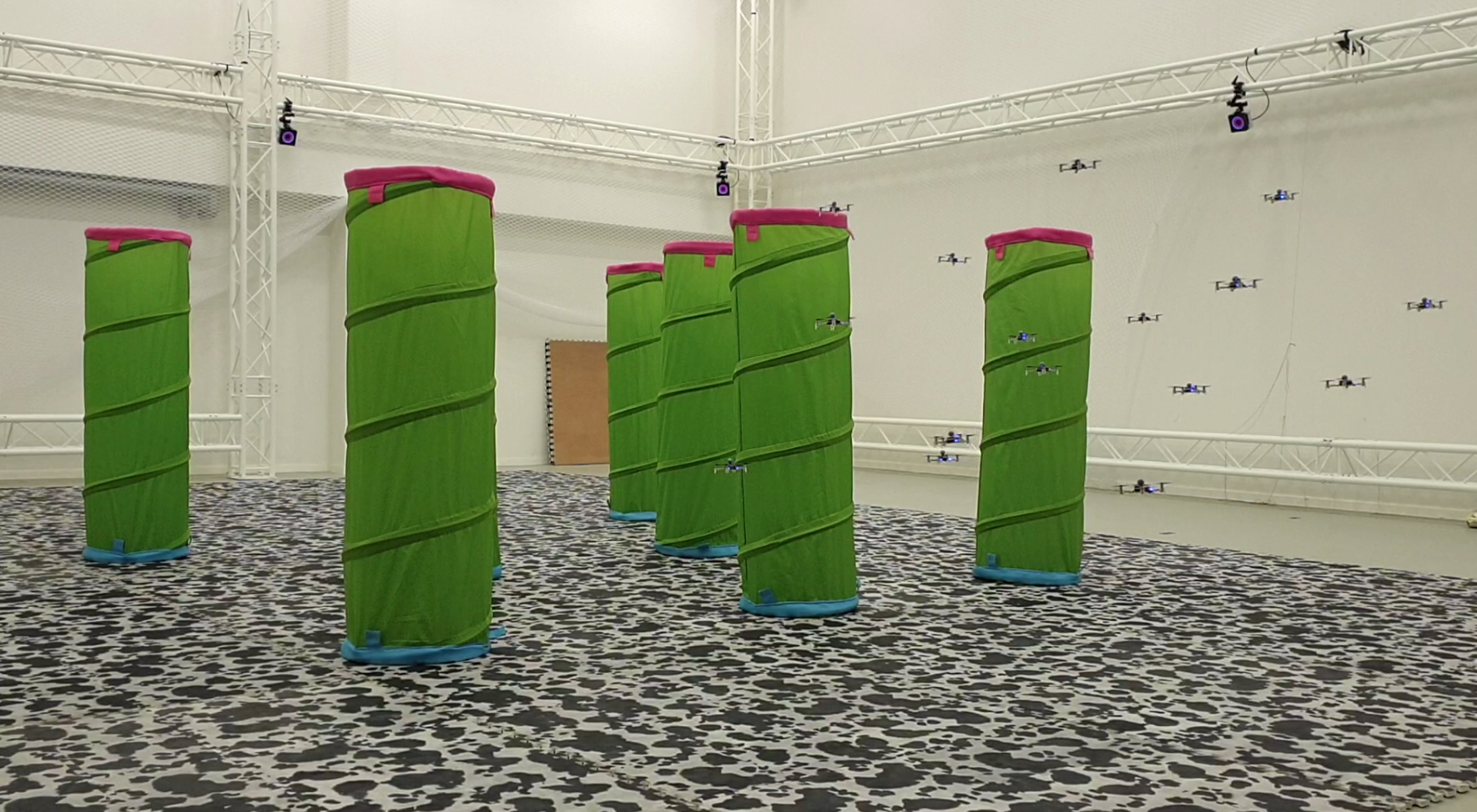
The goal was to pick up some packages and place them in the sleigh, and it all worked out pretty well. All the flying in the video is scripted using the python lib and positioning is done using Qualisys’ motion capture system with Active marker decks. The trajectories are hard coded and with some careful adjustments we managed to lift and fly the 4 crazyflies attached to the same present, even though it was a bit wobbly from time to time. Getting the present into the sleigh was not as easy, and we might have taken some short cuts here as well as when attaching/removing lines.
Picking up the second package needed some precision, and it went incredibly well, on the first try! The present was very light and needed someone to hold it, to prevent it from moving when the Crazyflie approached.
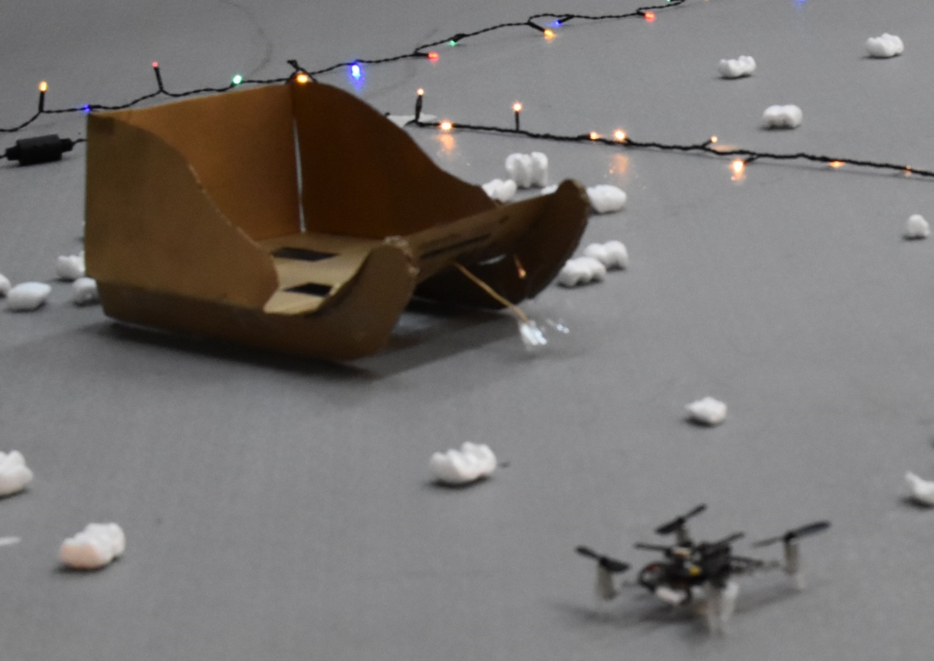
Getting the sleigh off
Our first tries included 5 strings attached to the sleigh, but it was difficult to get the right tension at the right time to have the UAVs actually pull the weight. Here came the “rubber band solution”: we just attached all the strings to a rubber band, that was itself attached to the sleight. That way, the tension could get even when all the Crazyflies were in the air and ready to pull the sleight.
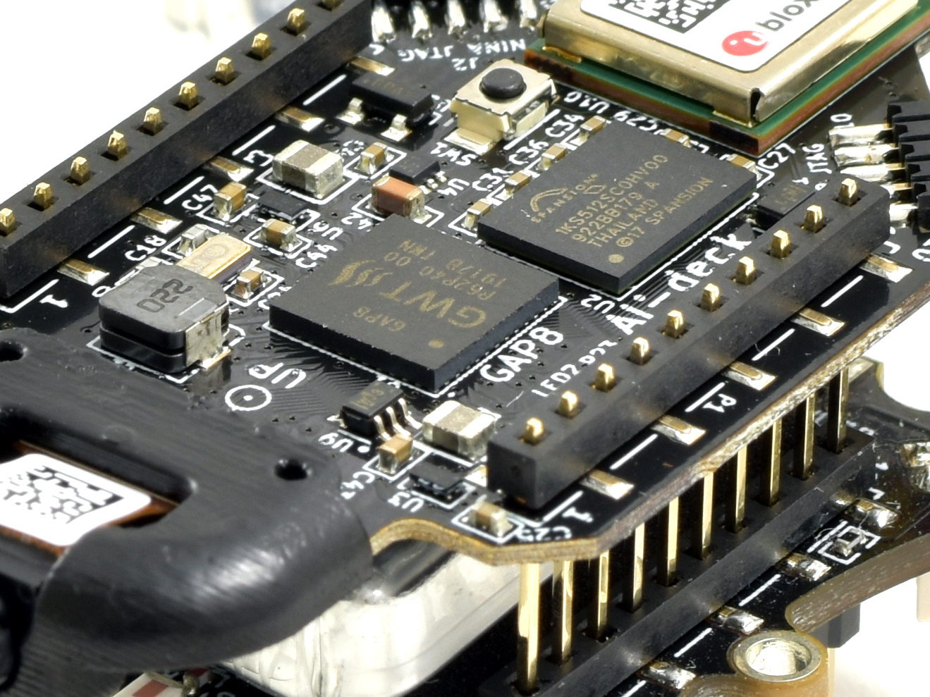
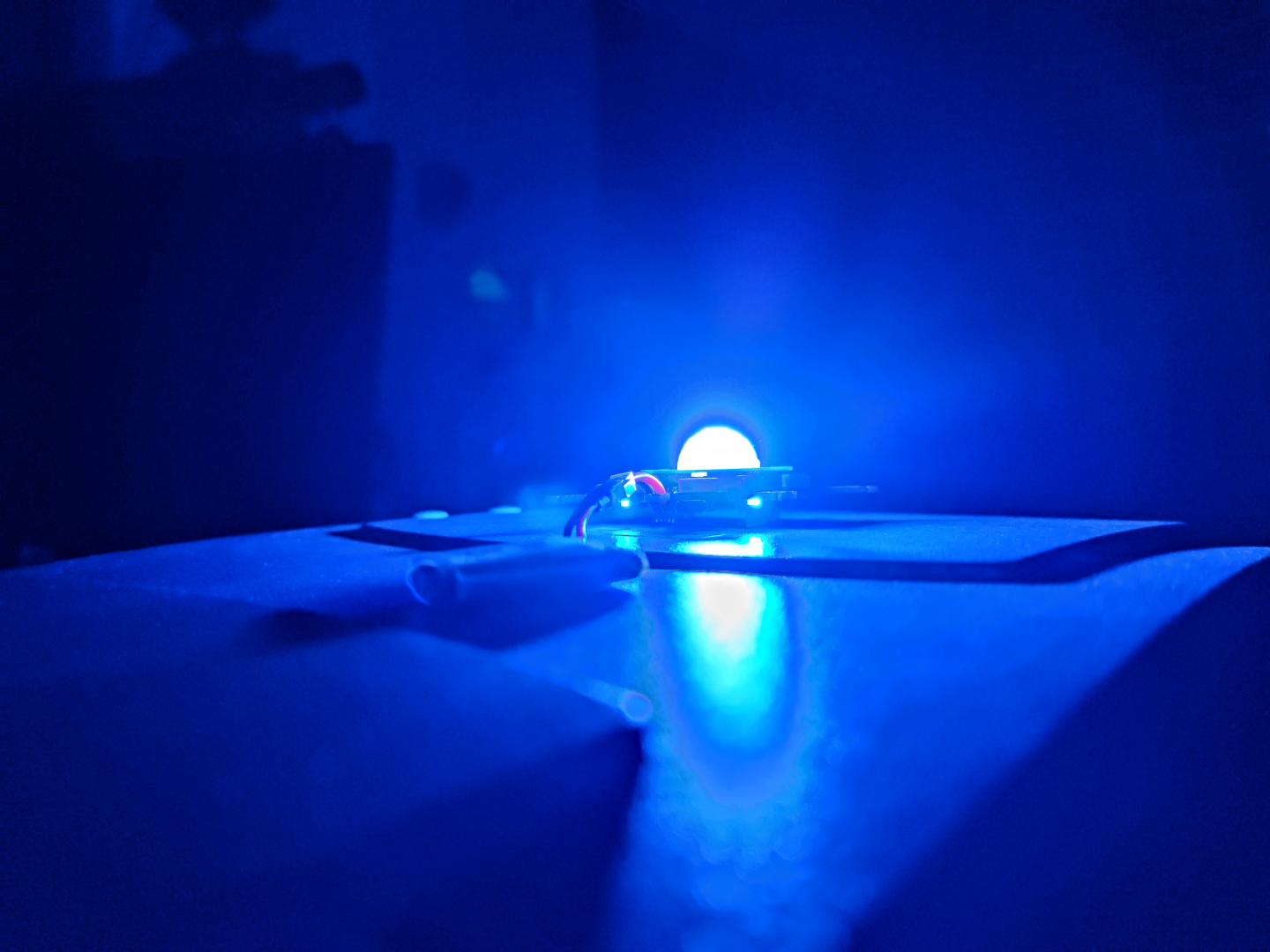
The AI deck camera/streamer
When we started this project, the intention was to run a neural network in the AI-deck to identify or classify the presents. We did not manage to get to a point where we had something that actually added value to the story, so we settled for just streaming the video from the AI-deck camera on the scouting drone instead.
The AI-deck example with color camera viewer is still under development, but if you want to give it a try you can take a look at the readme in the github repo.
Bloopers
And finally, as an added bonus, if you ever wonder how many tries it takes to make 5 Crazyflies pull a sleigh, here is a little behind-the-scenes video too!