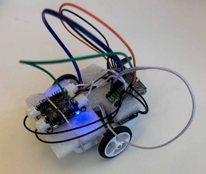
At Bitcraze, we spend a lot of time making things fly. Even though flying robots are, and will always be, fascinating to watch , every now and then it’s refreshing to try something different. Last Friday, I started exploring an idea that has been lying around for a while now: having a ground robot with the same Crazyflie infrastructure – the radio communication, the deck ecosystem and the cfclient connection. This robot is also known as the Crazyrat.
Fair warning: this is a first prototype, and it definitely looks like one. Jumper wires going in every direction, plastic foam and rubber bands to keep everything in place. But it drives, and it drives fast! That’s enough to call it a success and write about it.
Hardware
The entire vehicle was built around the Crazyflie Bolt 1.1, using its motor connectors, and specifically the S pins to drive a small H-bridge motor driver, enabling proper bidirectional DC motor control. To make it possible to drive the H-bridge, the motors must be configured as brushed.
For the motor driver, I used a Pololu DRV8833 Dual Motor Driver Carrier. I experimented with two different motor sets: one with a 75:1 gear ratio and one with 15:1. Even though the 75:1 motors offered better precision and were easier to drive, the 15:1 setup was the clear winner due to their speed.
The motors, the chassis and the power supply were taken from a Pololu 3pi+ robot.
Firmware
For the firmware, I used the Out-Of-Tree functionality of the crazyflie-firmware which makes it easy to integrate custom controllers. The controller itself is relatively simple. It maps pitch and yaw commands sent from the cfclient to throttle and steering respectively. Then, it sends the calculated values directly to the motors as PWM signals.
To test the prototype, I used a gamepad and drove it through the cfclient – no modifications are required. Here’s a video showing the capabilities of the Crazyrat using the 15:1 motor setup.
What’s Next
This project was a really fun learning experience on the potential and the limitations of the ground robots. These are some of the directions I plan to explore in the future:
Robust design – Design a proper chassis, clean up the wiring and make the whole vehicle smaller, to fit better in the Crazyflie ecosystem.
Deck integration – Use either the Lighthouse or the LPS deck for positioning and the Multi-Ranger deck for obstacle detection.
Experiment – Explore heterogeneous multi-agent swarming scenarios with the Crazyrat and the Crazyflie.
During my first Fun Friday as a Bitcraze intern in 2021, I discovered the musical note definitions in the Crazyflie firmware and thought about creating a musical performance using the Crazyflie’s motors, but never followed through.
A few weeks ago I decided to finally take it on as a Fun Friday Project with the slightly more ambitious goal of playing music across several Crazyflies at once.
crazyflie-jukebox takes a MIDI file, preprocesses it into motor frequency events, then uploads and plays the song by spinning the motors accordingly. Each Crazyflie contributes 4 voices (one per motor), so polyphony scales directly with your drone count.
I implemented this as a firmware app and a Python script using the work-in-progress cflib2 (running on Rust lib back-end). You can find the repository here, try it for yourself! Be aware that certain note combinations can cause the Crazyflie to move, flip, or take off unexpectedly.
Fitting music into 4 motors
The pipeline starts by parsing the MIDI file with mido. From there, an interactive track selection step shows you the instrument names, note counts, and ranges for each track so you can pick exactly which ones to include. The selected notes are then converted from MIDI note numbers into Hz frequencies that the motors can work with.
Each Crazyflie can only play 4 simultaneous voices (one per motor) so there’s some work involved in squeezing music into that constraint. I implemented a couple different voice allocation strategies: melodic priority, which keeps the bass and melody prioritized; voice stealing, which works like a LRU synth; and a simple round robin, which just assigns each new note to the next motor in turn, cutting off whatever was playing there. There’s also a frequency range problem to deal with: motors only reliably produce pitches in roughly the C4–B7 range, so notes outside that window get octave-shifted to fit.
Upload protocol
Events are packed into compact 6-byte structs containing a delta timestamp, motor index, an on/off flag, and the target frequency. These get streamed to the firmware app using the app channel in a simple START; events; END sequence. The Crazyflie app has a buffer limit of 5000 events, which effectively caps the length and complexity of what you can play. The 5000-event buffer was an arbitrary choice and you could probably get away with more, but it was enough for most songs I threw at it.
Synchronization
One of the trickier elements of this project was keeping Crazyflies synchronized. For starting in sync, I didn’t do anything special: no broadcast, no t-minus countdown, just sending start commands to each drone in sequence and relying on cflib2 to do it fast enough that the delay is negligible. That said, I’ve only tested with a small number of Crazyflies. With a larger fleet you’d probably need to implement something for the initial sync.
The real challenge is drift over time. The STM32’s crystal is rated at around 0.1% tolerance. This sounds tiny, but in the worst case, over a 1-minute song that’s already ~120 ms of drift between two drones. In a musical context, humans start noticing timing offsets around 20-30 ms; less for percussive sounds, and less for trained musicians. So left uncorrected, drift would become very audible well before the song ends.
To fix this, all clocks are reset to zero at song start. The host then periodically sends resync packets containing its own timestamp in microseconds, and each Crazyflie applies an offset correction to stay aligned, which as a bonus also irons out any initial start latency.
Rough edges
The biggest design constraint is that a single track can’t be split across Crazyflies, so if a track has more than 4 simultaneous voices, some get dropped. I thought of each Crazyflie as its own instrument, which made sense at the time, but it does mean a dense MIDI tracks can’t be split across multiple drones, which feels limiting in hindsight.
The usable pitch range is about 4 octaves (C4–B7), and propellers need to be attached for accurate pitch since the motors need load to produce the right frequencies, which makes the whole thing a bit unsafe. Certain note combinations can cause a drone to move, flip, or behave unpredictably. Only brushed motors are supported, and there’s a hard 71-minute per-song limit on clock sync. But honestly, if you’re sitting there listening to a 71-minute song on your Crazyflie, the clock drift is the least of your problems.
With spring just around the corner, we thought it was the perfect excuse to make our Crazyflies bloom. The result is a small swarm demo where each drone flies a 3D flower trajectory, all coordinated from a single Crazyradio 2.0. This blog post walks through how it works and highlights two things that made it possible: the new Color LED deck and the Crazyflie Rust library.
The Color LED deck
There are two Color LED decks for the Crazyflie – one mounted on top and one on the bottom – each with its own individually controllable LED via the standard parameter interface. In this demo we use the one mounted on the bottom to give color to the flowers, along with the Lighthouse deck for accurate positioning in space.
The deck opens up a lot of creative possibilities for swarm demos as well as clear visual feedback about what each drone is doing.
Fast swarm connections with the Crazyflie Rust library
Getting five drones connected quickly on a single Crazyradio used to be a real bottleneck. The Crazyflie Rust library introduces a lazy-loading parameter system. Parameter values are not downloaded at connect time; instead, they are fetched only if the API user explicitly accesses them.
Additionally, caching the TOC (Table of Contents) makes it trivial to persist it locally and reuse it on every subsequent connection. In practice this means that after connecting to each drone once, all future connections are nearly instantaneous. The cache is keyed by the TOC’s CRC32 checksum, so it automatically stays valid as long as the firmware doesn’t change, and it’s identical between drones with the same checksum.
The library also uses Tokio’s async runtime, which means all Crazyflie connections start at the same time without waiting for each other. Combined with generally higher communication performance in the Rust implementation, these features significantly reduce the startup overhead, making the swarm feel reliable and responsive, which would require much more effort with the current Python library.
Generating the trajectories
The flower shapes are generated in Python using this script. It produces two .json files per drone (one stem{n} and one petals{n}) containing all the waypoints to fly through. The trajectories are then uploaded to the drone as compressed poly4d segments, a compact format that the Crazyflie’s onboard high-level commander can execute autonomously. Both trajectories are expressed relative to each drone’s initial position, so the formation geometry is entirely determined by where you place the drones on the ground before takeoff.
Putting them all together
The flight sequence is pretty straightforward:
1. Build the trajectories as waypoints on the host.
2. Connect to all drones simultaneously.
3. Upload each drone’s compressed trajectories in parallel.
4. Fly the trajectories while switching the LED colors.
Everything after the connection is driven by Tokio’s join_all, so the swarm stays in sync without any explicit synchronization logic – the drones are just given the same commands at the same time.
The full source code is available at this repository (Python for trajectory generation, Rust for flying).
We’re excited about where the Rust library is heading. It’s improving the communication with the Crazyflie and allows us to increase dramatically the number of Crazyflies per Crazyradio, leading to bigger and more reliable swarms. If you build something cool with it, let us know!
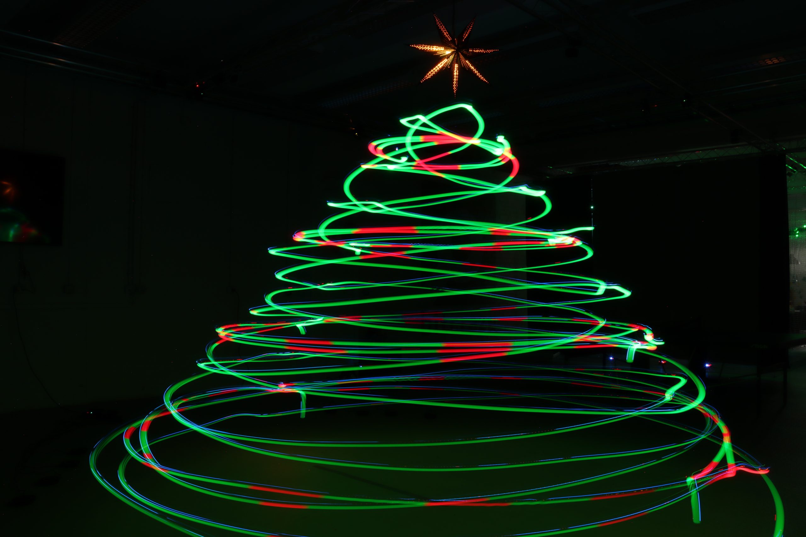
Christmas is getting close, and while most people are just starting to hang lights and decorate their tree, we decided to go a little bigger and a whole lot brighter. Instead of adding tinsels and ornaments, we set up a swarm of 8 Crazyflie 2.1 Brushless drones with the upcoming Color LED decks along with some long-exposure photography magic, and decorated our flying arena with a Christmas tree made of Crazyflies.
How it works
The project is split into two parts: the firmware side that controls the Color LED decks and the script that is responsible for the choreography of the swarm.
The Firmware
Instead of lighting the LEDs based on time or commands, each Crazyflie uses its 3D position to decide on the correct color. This makes the whole communication with the central computer easier. Inside the firmware, multiple virtual spheres are created in the flight arena, just like ornaments floating in a tree-shaped structure. Whenever a Crazyflie flies into one of these spheres, its Color LED deck switches instantly from green to red. When it flies back out, it glows green again. Since we’re taking a long-exposure photo, the whole color pattern begins when the drones are ready to perform the choreography and stops when they start landing.
The Script
The python script is pretty simple. It commands a swarm of Crazyflies to perform a coordinated spiral choreography resembling a Christmas tree outline in 3D space. Each drone takes off to a different height, flies in spiraling circular layers, and changes radius as it rises and descends, forming the visual structure of a cone when viewed from outside. To pull this off with the current state of the cflib, we used 3 Crazyradios 2.0 and the high level commander.
A Testbed for Crazyradio 2.0 Improvement
Lately, we have been looking again at improving the radio communication with the Crazyflie. A prototype featuring a new USB communication mode for the Crazyradio was ready just in time for testing with the Christmas tree demo.
This new mode makes Crazyradio 2.0 much more efficient when communicating with swarms. With it, we were able to fly the same demo using only one Crazyradio 2.0 instead of 3 with the connection time to the swarm greatly accelerated. This demonstrates the efficiency of the new mode.
The new mode is called “inline setting mode” since it works by inlining all radio settings with the packet data, negating the need to issue time-costly USB setup requests. It is currently a Pull Request to Crazyradio 2.0 and the Rust Crazyradio driver. Support for Crazyswarm/ROS and CFLib will be implemented and when we know that the protocol works out for all libs, we will merge and release support for the new mode. It will be enabled by default so you will get the benefits from upgrading the Crazyradio 2.0 firmware and lib. We will talk more about it when it is released, in the mean time do not hesitate to test and feedback on the PRs ;-).
Demo source code
You can find the project’s repository as well as the rust version on Github. The python version was used for the picture and video, and the Rust one behaves identically.
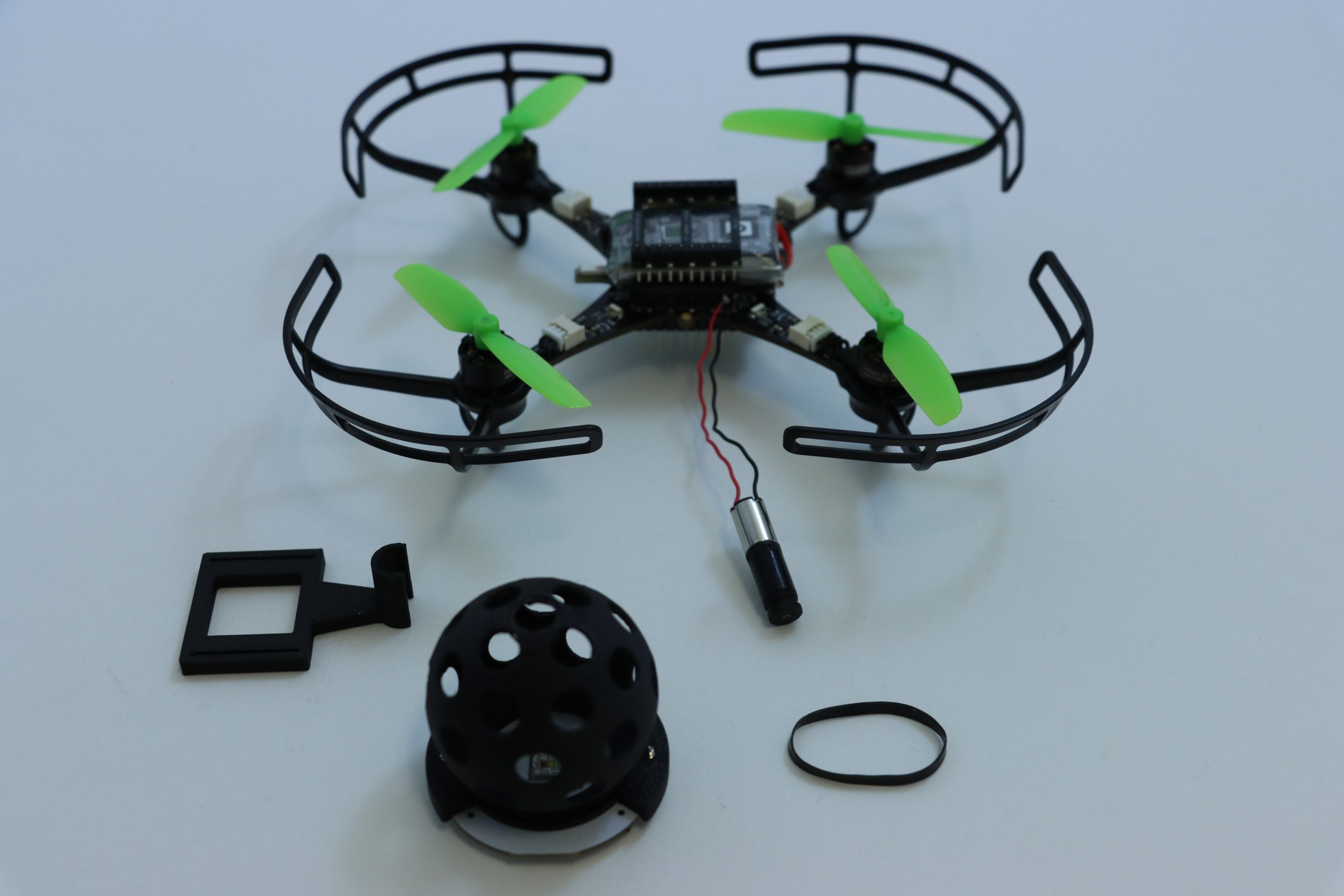
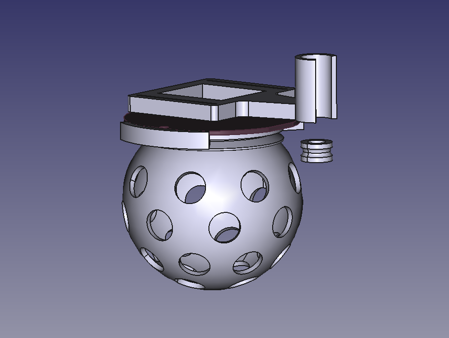
It’s always a good feeling to wrap up the week with a Fun Friday project – especially when it involves some questionable mechanical additions to a Crazyflie platform. This time, I decided to test the capabilities of the upcoming Color LED deck by turning it into a Disco deck.
Mechanics
The core of the Disco Deck is pretty simple: a 3D-printed disco ball mounted directly on top of the Color LED Deck with a couple of screws. To bring it to life, I added a Sub-Micro Plastic Planetary Gearmotor and used a rubber band as a drive belt to transfer the rotation. It’s a lightweight, low-tech solution that works surprisingly well with the Crazyflie 2.1 Brushless. All the structural parts were designed to be easily 3D printed in PLA, and they fit on a single print plate for a quick build. You can find all the part files here.
Electronics & Firmware
On my first attempt, I connected the motor directly to VCC and GND, which meant it started spinning as soon as the Crazyflie powered up. This turned out to be a problem as the vibrations prevented the Crazyflie from completing its initialization sequence, since it needs to remain completely still for about one second at startup. The proper fix was to connect the motor to one of the GPIO pins (IO_4) along with GND. For the firmware, I added a new deck driver for setting the IO_4 output to low during initialization and controlling it through a parameter.
Next Steps
The biggest limitation of the current Disco Deck design is the landing. The disco ball extends below the length of the Crazyflie 2.1 Brushless legs, which means the drone can’t take off or land horizontally – not even when using the standard Crazyflie 2.1 Brushless charging dock. To fix this, I’m planning to design a custom charging dock that also works as a stable landing platform for the Party drone.
If you’re interested on the process, you can check out the project repository for any updates.
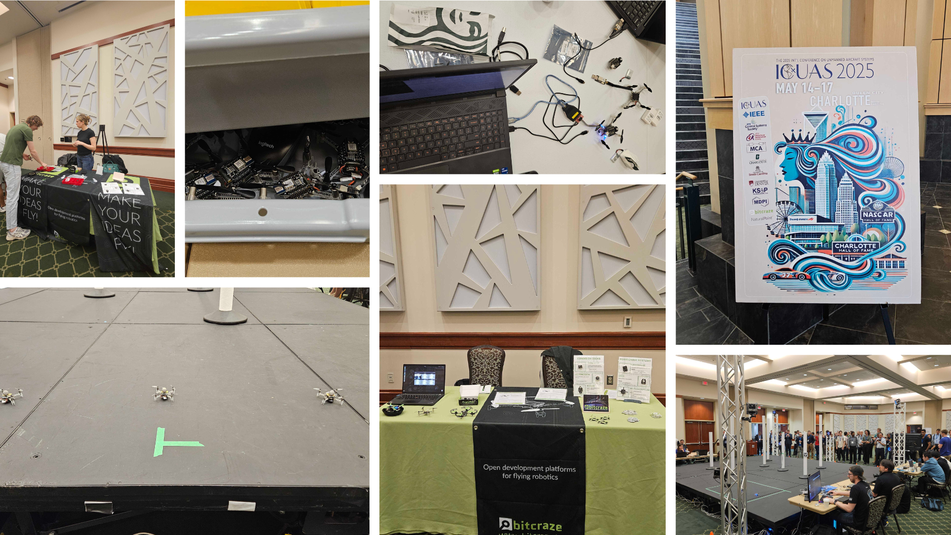
As we mentioned in a previous blog post, the last couple of weeks have been full of exciting events in the US. We first began our adventure in Charlotte, North Carolina, where we attended the International Conference on Unmanned Aircraft Systems (ICUAS), as platinum sponsors.
We were especially thrilled to be involved because the final stage of the conference’s competition featured Crazyflies, which played a central role in the challenge.
The ICUAS UAV Competition
This year’s competition simulated a search mission in an urban environment. The goal was for teams to identify ArUco markers placed on multiple obstacles, while maintaining line-of-sight and communication among a swarm of three Crazyflies.
Each team’s UAVs launched from a designated base, navigated a known environment, and attempted to locate several targets. The drones relied on an OptiTrack system for positioning and used the AI deck as a camera for image recognition. Constant communication between the base and all UAVs was required throughout the mission.
The event, organized by the LARICS team, combined both simulation and real-world implementation. Their hard work ensured that competitors could smoothly transition their systems from digital models to actual flying drones. What followed was an intense and fun two-day hackathon.
Although the ICUAS UAV Competition drew interest from 26 teams globally, only five finalist teams made it to Charlotte to run their scenarios with real drones. In the end, it was Team Aerial Robotics from the Indian Institute of Technology Kanpur (IITK) who took home first place—congratulations to them!
While the event went smoothly overall, some communication challenges cropped up—solved creatively by placing a radio in the center of the arena. Battery management was also key, with fully charged packs being a hot commodity to maximize flight time.
Research and Presentations
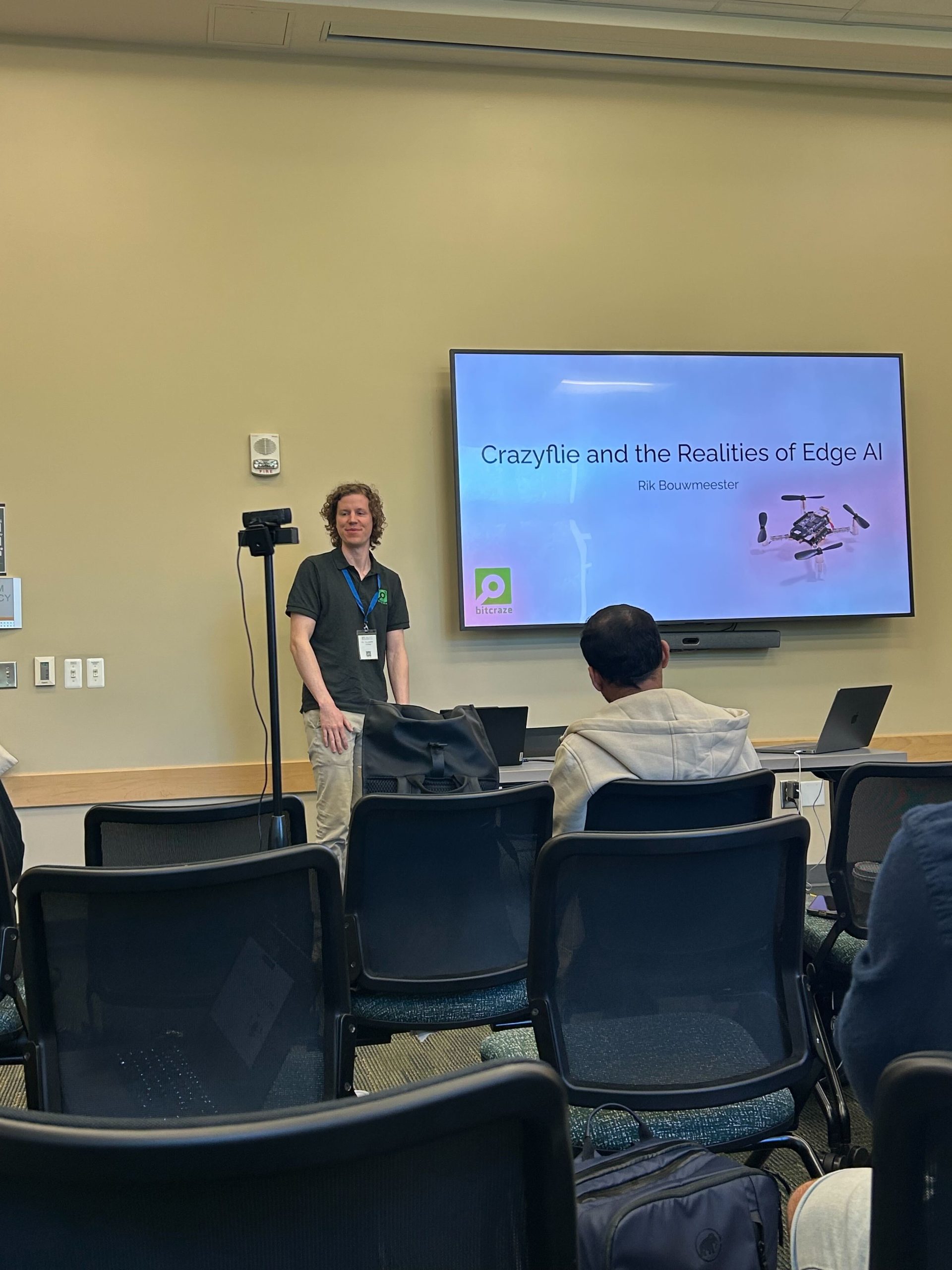
Alongside the competition, the conference featured a wide range of research presentations. We were proud to see Rik present on the AI deck during a workshop focused on embodied AI.
One of the highlights was the Best Paper Award, which—although we missed the talk, was awarded to a team from Queen’s university using the Crazyflie to simulate drone landings on ocean waves. You can read their fascinating paper here: https://arxiv.org/abs/2410.21674
Final Thoughts
Overall, ICUAS 2025 was a great experience—full of innovation, collaboration, and of course, plenty of flight time. We’re grateful to the organizers, competitors, and everyone who stopped by our booth. Until next time!
Drones can perform a wide range of interesting tasks, from crop inspection to search-and-rescue. However, to make drones practically attractive they should be safe and cheap. Drones can be made safer by reducing their size and weight. This causes less damage in a collision with people or the environment. Additionally, being cheap means that the drones can take more risk – as it is less expensive to lose one – or that they can be deployed in larger numbers.
To function autonomously, such a drone should at least have some basic navigation capabilities. External position references such as GPS or UWB beacons can provide these, but such a reference is not always available. GPS is not accurate enough in indoor settings, and beacons require prior access to the area of operation and also add an additional cost.
Without these references, navigation becomes tricky. The typical solution is to have the drone construct a map of its local environment, which it can then use to determine its position and trajectories towards important places. But on tiny drones, the on-board computational resources are often too limited to construct such a map. How, then, can these tiny drones navigate? A subquestion of this – how to follow previously traversed routes – was the topic of my MSc thesis under supervision of Kimberly McGuire and Guido de Croon at TU Delft, and my PhD studies. The solution has recently been published in Science Robotics – “Visual route following for tiny autonomous robots” (TU Delft mirror here).
Route following
In an ideal world, route following can be performed entirely by odometry: the measurement and recording of one’s own movements. If a drone would measure the distance and direction it traveled, it could just perform the same movements in reverse and end up at its starting place. In reality, however, this does not entirely work. While current-day movement sensors such as the Flow deck are certainly accurate, they are not perfect. Every time a measurement is taken, this includes a small error. And in order to traverse longer distances, multiple measurements are summed, which causes the error to grow impractically large. It is this integration of errors that stops drones from using odometry over longer distances.
The trick to traveling longer distances, is to prevent this buildup of errors. To do so, we propose to let the drone perform ‘visual homing’ maneuvers. Visual homing is a control strategy that lets an agent return to a location where it has previously taken a picture, called a ‘snapshot’. In order to find its way back, the agent compares its current view of the environment to the snapshot that it took earlier. The trick here is that the difference between these two images smoothly grows with distance. Conversely, if the agent can find the direction in which this difference decreases, it can follow this direction to converge back to the snapshot’s original location.
The difference between images smoothly increases with their distance.
So, to perform long-distance route following, we now command the drone to take snapshots along the way, in addition to odometry measurements. Then, when retracing the route, the drone will routinely perform visual homing maneuvers to align itself with these snapshots. Because the error after a homing maneuver is bounded, there is now no longer a growing deviation from the intended path! This means that long-range route following is now possible without excessive drift.
Implementation
The above mentioned article describes the strategy in more detail. Rather than repeat what is already written, I would like to give a bit more detail on how the strategy was implemented, as this is probably more relevant for other Crazyflie users.
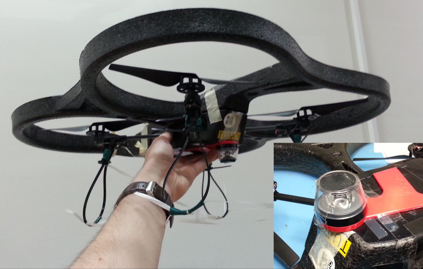
The main difference between our drone and an out-of-the-box one, is that our drone needs to carry a camera for navigation. Not just any camera, but the method under investigation requires a panoramic camera so that the drone can see in all directions. For this, we bought a Kogeto Dot 360. This is a cheap aftermarket lens for an older iPhone that provides exactly the field-of-view that we need. After a bit of dremeling and taping, it is also suitable for drones.
ARDrone 2 with panoramic camera lens.
The very first visual homing experiments were performed on an ARDrone 2. The drone already had a bottom camera, to which we fitted the lens. Using this setup, the drone could successfully navigate back to the snapshot’s location. However, the ARDrone 2 hardly qualifies as small as it is approximately 50cm wide, weighs 400 grams and carries a Linux computer.
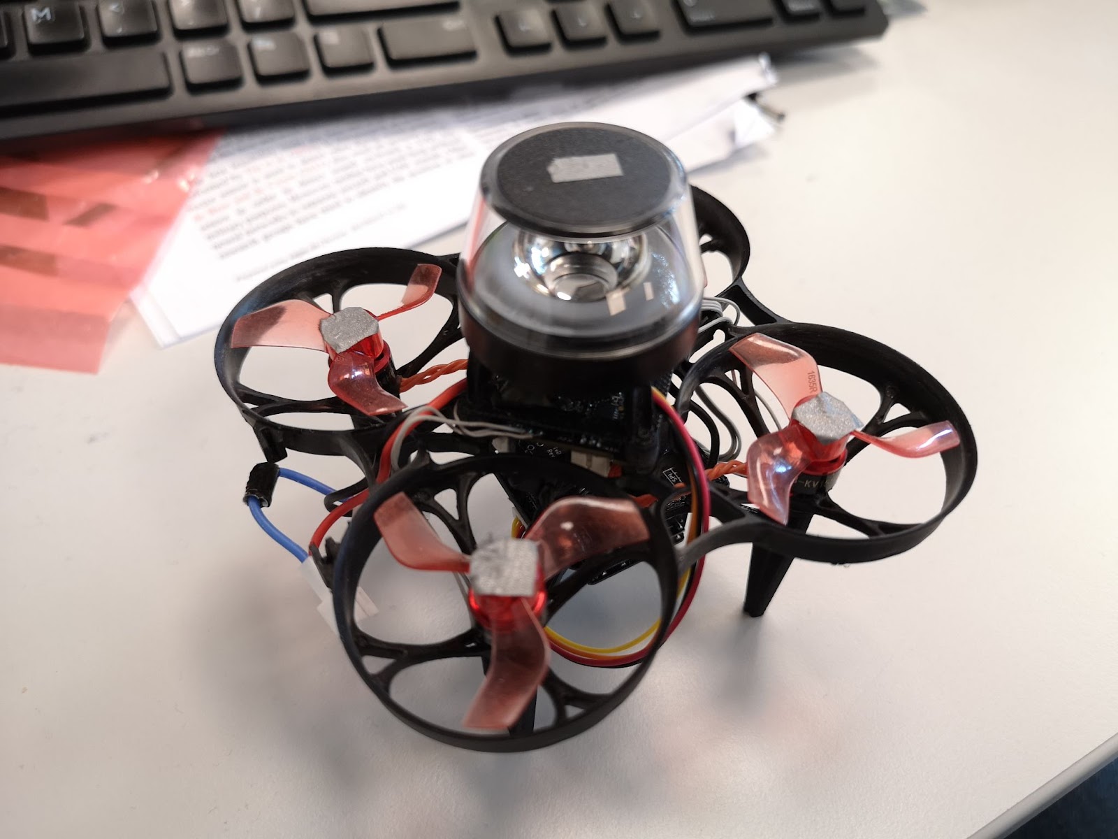
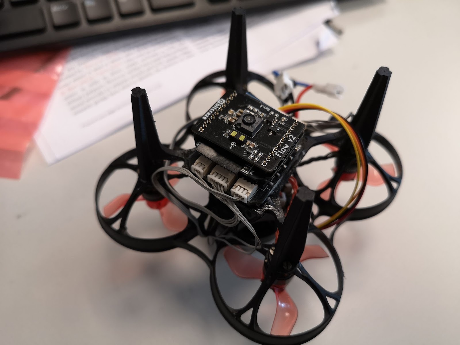
Eachine Trashcan with panoramic camera and Flow deck.
To prove that the navigation method would indeed work on tiny drones, the setup was downsized to a Crazyflie 2.0. While this drone could take off with the camera assembly, it would become unstable very soon as the battery level decreased. The camera was just a bit too heavy. Another attempt was made on an Eachine Trashcan, heavily modified to support both the camera, a flowdeck and custom autopilot firmware. While this drone had more than enough lift, the overall reliability of the platform never became good enough to perform full flight experiments.
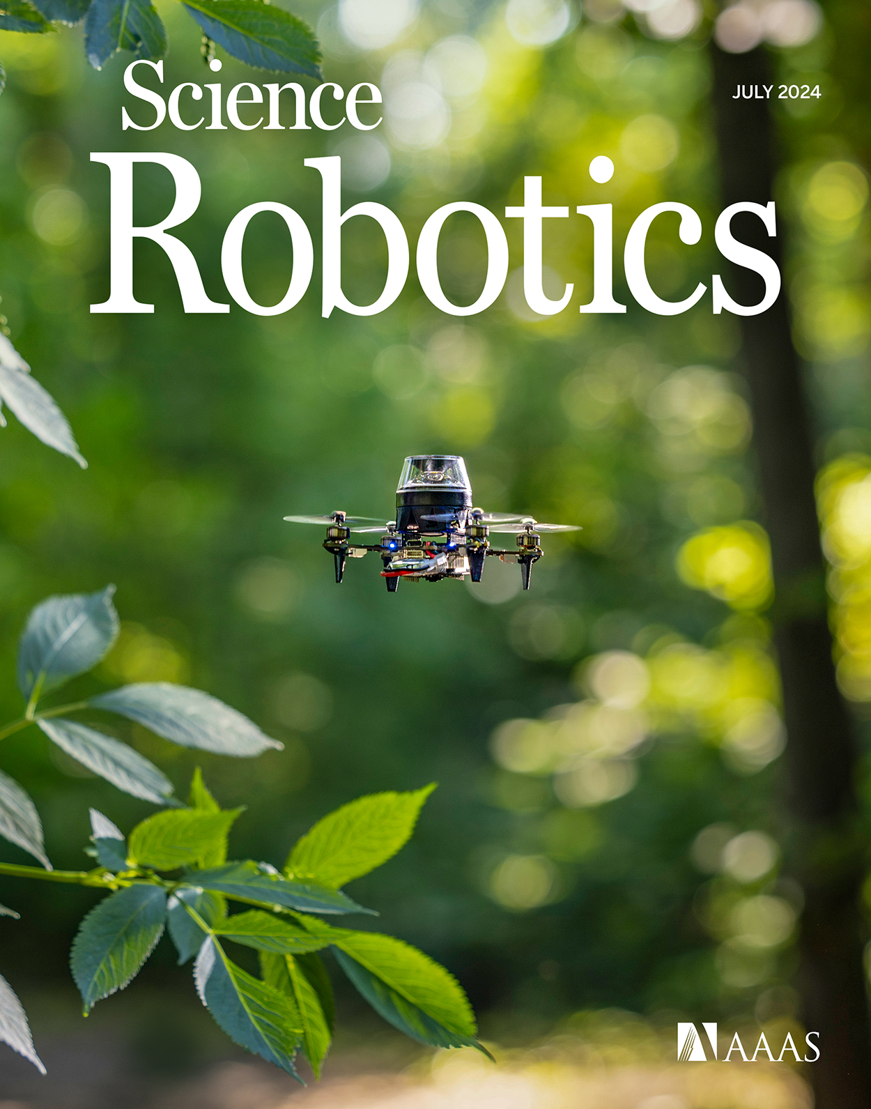
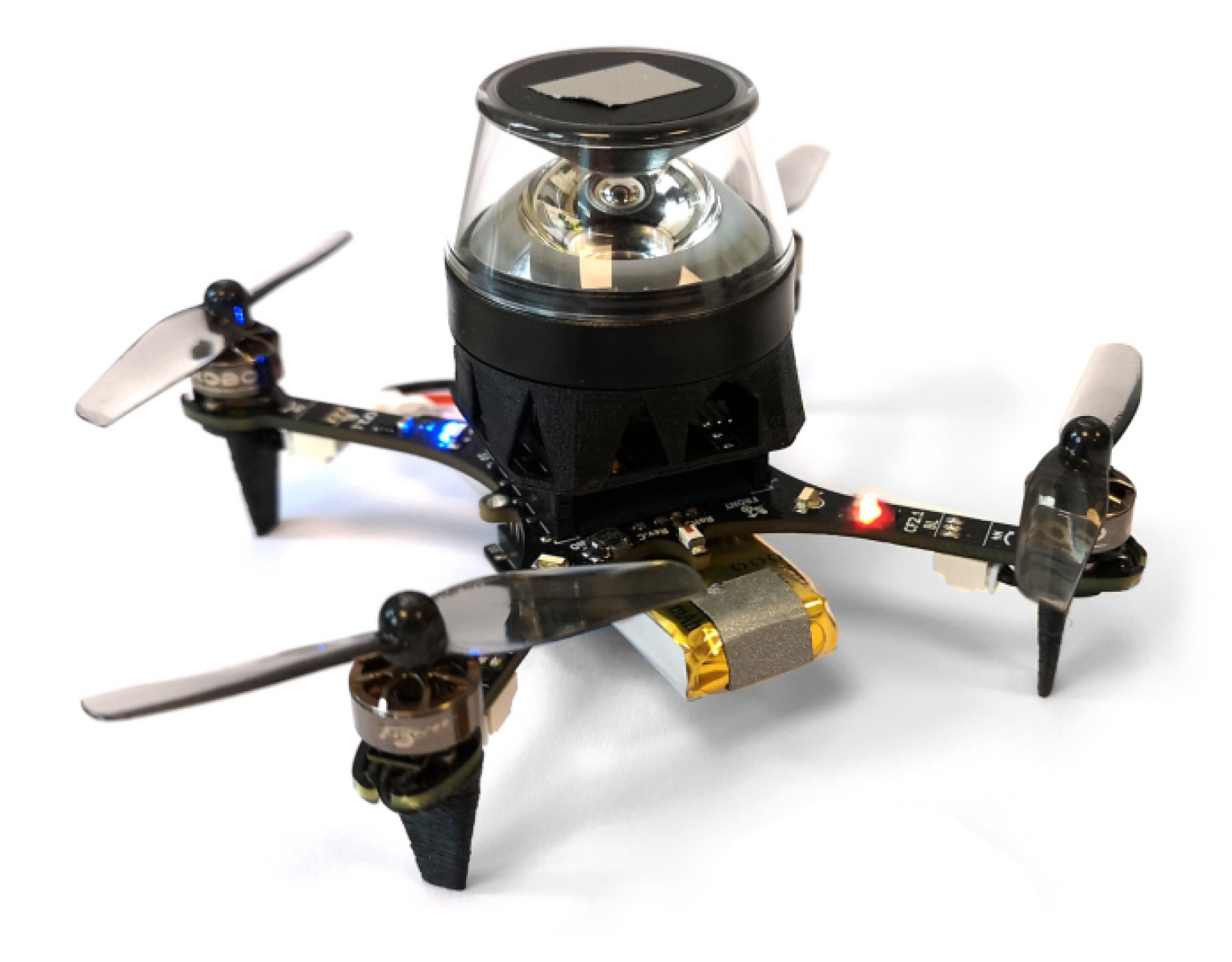
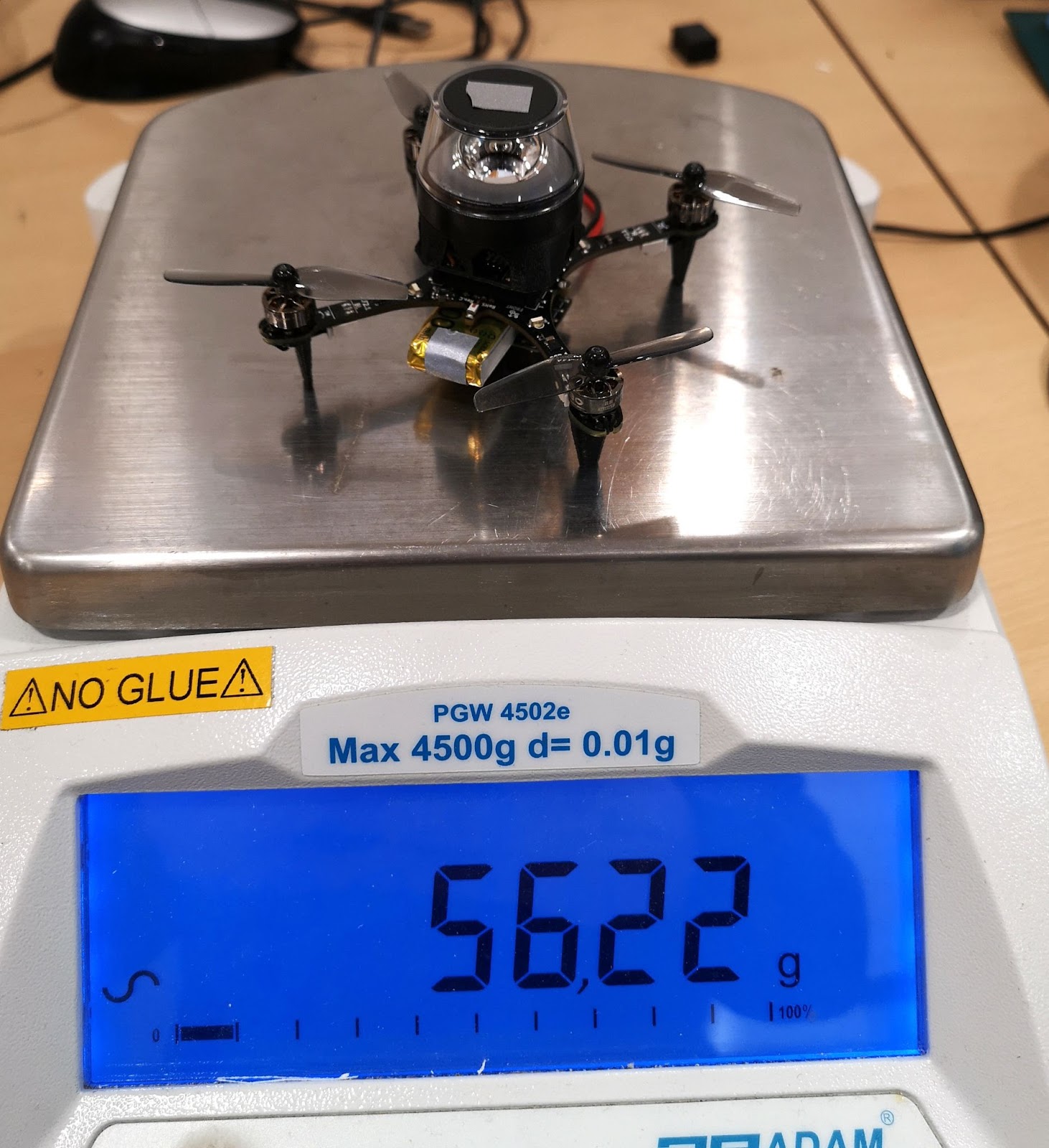
After discussing the above issues, I was very kindly offered a prototype of the Crazyflie Brushless to see if it would help with my experiments. And it did! The Crazyflie brushless has more lift than the regular platform and could maintain a stable attitude and height while carrying the camera assembly, all this, with a reasonable flight time. Software-wise it works pretty much the same as the regular Crazyflie, so it was a pleasure to work with. This drone became the one we used for our final experiments, and was even featured on the cover of the Science Robotics issue.
Crazyflie Brushless prototype with panoramic camera.
With the hardware finished, the next step was to implement the software. Unlike the ARDrone 2 which had a full Linux system with reasonable memory and computing power, the Crazyflie only has an STM32 microcontroller that’s also tasked with the flying of the drone (plus an nRF SoC, but that is out of scope here). The camera board developed for this drone features an additional STM32. This microcontroller performed most of the image processing and visual homing tasks at a framerate of a few Hertz. However, the resulting guidance also has to be followed, and this part is more relevant for other Crazyflie users.
To provide custom behavior on the Crazyflie, I used the app layer of the autopilot. The app layer allows users to create custom code for the autopilot, while keeping it mostly decoupled from the underlying firmware. The out-of-tree setup makes it easier to use a version control system for only the custom code, and also means that it is not as tied to a specific firmware version as an in-tree process.
The custom app performs a small number of crucial tasks. Firstly, it is responsible for communication with the camera. Communication with the camera was performed over UART, as this was already implemented in the camera software and this bus was not used for other purposes on the Crazyflie. Over this bus, the autopilot could receive visual guidance for the camera and send basic commands, such as the starting and stopping of image captures. Pprzlink was used as the UART protocol, which was a leftover from the earlier ARDrone 2 and Trashcan prototypes.
The second major task of the app is to make the drone follow the visual guidance. This consisted of two parts. Firstly, the drone should be able to follow visual homing vectors. This was achieved using the Commander Framework, part of the Stabilizer Module. Once the custom app was started, it would enter an infinite loop which ran at a rate of 10 Hertz. After takeoff, the app repeatedly calls commanderSetSetpoint to set absolute position targets, which are found by adding the latest homing vector to the current position estimate. The regular autopilot then takes care of the low-level control that steers the drone to these coordinates.
The core idea of our navigation strategy is that the drone can correct its position estimate after arriving at a snapshot. So secondly, the drone should be able to overwrite its position estimate with the one provided by the route-following algorithm. To simplify the integration with the existing state estimator, this update was implemented as an additional position sensor – similar to an external positioning system. Once the drone had converged to a snapshot, it would enqueue the snapshot’s remembered coordinates as a position measurement with a very small standard deviation, thereby essentially overwriting the position estimate but without needing to modify the estimator. The same trick was also used to correct heading drift.
The final task of the app was to make the drone controllable from a ground station. After some initial experiments, it was determined that fully autonomous flight during the experiments would be the easiest to implement and use. To this end, the drone needed to be able to follow more complex procedures and to communicate with a ground station.
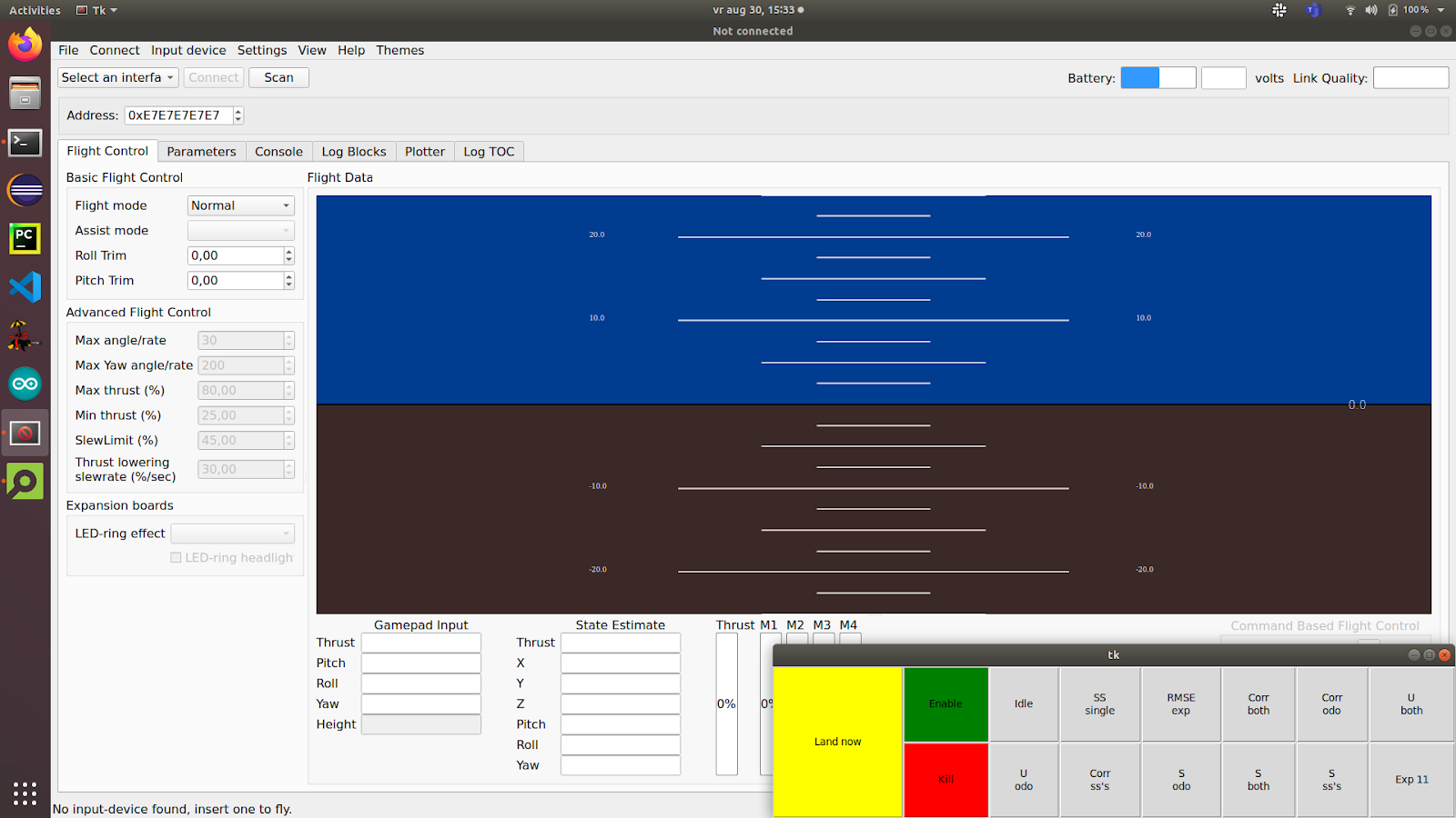
Because the cfclient provides most of the necessary functions, it was used as the basis for the ground station. However, the experiments required extra controls that were of course not part of a generic client. While it was possible to modify the cfclient, an easier solution was offered by the integrated ZMQ server. This server allows external programs to communicate with the stock cfclient over a tcp connection. Among the possibilities, this allows external programs to send control values and parameters to the drone. Since the drone would be flying autonomously and therefore low-frequencies would suffice, the choice was made to let the ground station set parameters provided by the custom app. To simplify usability, a simple GUI was made in python using the CFZmq library and Tkinter. The GUI would request foreground priority such that it would be shown on top of the regular client, making it easy to use both at the same time.
Cfclient with experimental overlay (bottom right).
To perform more complex experiments, each experiment was implemented as a state machine in the custom app. Using the (High-level) Commander Framework and the navigation routines described above, the drone was able to perform entire experiments from take-off to landing.
Using the hardware and software described above, we were able to perform the route-following experiments. The drone was commanded to fly a preprogrammed trajectory using the Flow deck, while recording odometry and snapshot images. Then, the drone was commanded to follow the same route in reverse, by traveling short sections using dead reckoning and then using visual homing to correct the incurred drift.
As shown in the article, the error with respect to the recorded route remained bounded. Therefore, we can now travel long routes without having to worry about drift, even under strict hardware limitations. This is a great improvement to the autonomy of tiny robots.
I hope that this post has given a bit more insight into the implementation behind this study, a part that is not often highlighted but very interesting for everyone working in this field.
This Christmas, Bitcraze is sending out a callout to Santa. As it turns out, one of our Brushless prototypes has a lifelong dream of becoming one of Santa’s reindeer. In a hopeful attempt to fulfill its wishes, we shot a video to prove that it’s ready for Santa’s most elite aerial team!
Imagine a tiny, determined drone with big dreams, practicing its sleigh route moves with the intensity of an Olympic athlete. Our little Brushless is proving it has what it takes to join the North Pole’s premier delivery squad.
Going through small openings, avoiding obstacles, and flying in perfect precision are skills that any good reindeer should have – but here, the Brushless accomplish this in an autonomous flight, and in a much smaller and more practical package than Rudolph and consorts.
Of course, there’s some technical magic behind this Christmas miracle. For this project, we relied on stock firmware and Python library, taking advantage of the new spiral and constant velocity features (check out the GitHub PR here). These features added variety and fluidity to the maneuvers, moving beyond straight lines and making the flight more interesting. By using the high-level commander, we took a simpler approach compared to trajectory optimization, which we’ve used in past Christmas videos. Trajectory optimization would have been far more difficult for this project due to the unique challenges of the flight path—namely its length and the need for pinpoint accuracy near obstacles and through gates.
Positioning relied on four Lighthouse base stations, which we used to manually locate the Christmas wreaths by holding the drone within each one to log their exact coordinates. This project also gave us the opportunity to further integrate the Brushless into our firmware and Python libraries, setting the stage for a smoother launch in the new year. The Brushless impressed us yet again during this project. Even though we’ve tested it extensively in the past, seeing it navigate tight gates with such precision and handle the demanding flight path reinforced just how capable it is. Working with it in this setting has made us even more excited to release it soon and share its potential with everyone.
Santa, if you’re reading this, we think we’ve found your next top reindeer recruit. You can watch the full audition tape here or below:
And if you think what you just saw is a pretty straight-forward and easy path, think again! This year’s blooper video highlights the resilience of the Crazyflie 2.1 Brushless and the fast, iterative workflow we used for this project. Since testing reliability and resilience was a key goal, we adopted a workflow that allowed for quick scripting, flying, and adjusting—often completing the cycle in just minutes. This approach made crashes more likely, especially during the spiral sections where the drone struggled to keep up and started cutting corners. While we resolved the issue by slowing those sections down, we suspect that more aggressive tuning of the Mellinger controller could have helped the drone maintain speed without cutting corners. The Brushless managed some impressive recoveries, but even minor collisions usually meant it couldn’t keep pace with the rest of the trajectory. After all the trial and error, we had a stable and reliable setup that not only performed well for the demo but also flew beautifully when we showed it to our families at the Christmas party.
Here is what our Brushless could endure during training:
Merry Christmas from all of us at Bitcraze – where even our prototypes have holiday dreams!
We have some very busy weeks behind us and ahead! As we are working hard on releasing the new CF Brushless, we have been preparing for the upcoming ROSCon in Odense Denmark next week (see this previous blogpost) and we also featured on the latest OpenCV live episode as well! So more about both in this blogpost.
OpenCV Live! Demo Driven Development
We were featured as guests on the latest OpenCV Live! episode hosted by Phil Nelson and Satya Mallick, where we went through a bit of the history of the start of Bitcraze and all of the (crazy) demos done with the Crazyflie in the last decade. We have done a similar topic for our latest developer meeting, but for this episode we put the focus more on vision based demos, since OpenCV has been definitely used in the past at Bitcraze for various reasons! Just type in OpenCV in the top right search barto check out any of the blogs we have written.
During the OpenCV live episode of the 10th of October, Arnaud and Kimberly told the backstories of these demos that went from a manual flight fail where Arnaud flew the Crazyflie 1.0 in Marcus’ hair, using OpenCV and Aruco markers for positioning to flying a swarm in your kitchen. It was really fun to do and alos one lucky listener managed to answer the two questions the host Phil asked at the end, namely “Where does the name Crazyflie come from?” and “Why is the last part (‘-flie’) spelled this way?” and won a STEM ranging bundle. If you’d like to know the answers, go and watch the latest OpenCV! Live episode ;) Enjoy!
ROSCon – What to expect?
So next week we will be present as Silver Sponsor at ROSCon Odense, namely on Monday 21th and Wednesday 23rd of October. The Bitcraze booth will be located on number 21 so that should be near the coffee break place! We will have are old trusty cage with some upgrades with a nice ROS demo which is similar to the one explained in this Crazyflie ROS tutorial we have written a while ago, but then the swarming variant of it. We also hope to show a Brushless Crazyflie Prototype, and a new camera deck prototype, along with anything else we can find lying around at our office :D.
Moreover, Arnaud will be given a presentation on the lighthouse positioning system, namely at Wednesday 23rd of October 14:40 (2:30 pm) called ‘The Lighthouse project: from Virtual Reality to Onboard Positioning for Robotics’. The lighthouse positioning system will also be the system that we will demo at our booth so if you’d like to see it for yourself, or perhaps (during downtime) hack around together with us, you are more than welcome to do so! Check out the Bitcraze ROSCon Eventpage for more details about our demo or the hardware we will show.
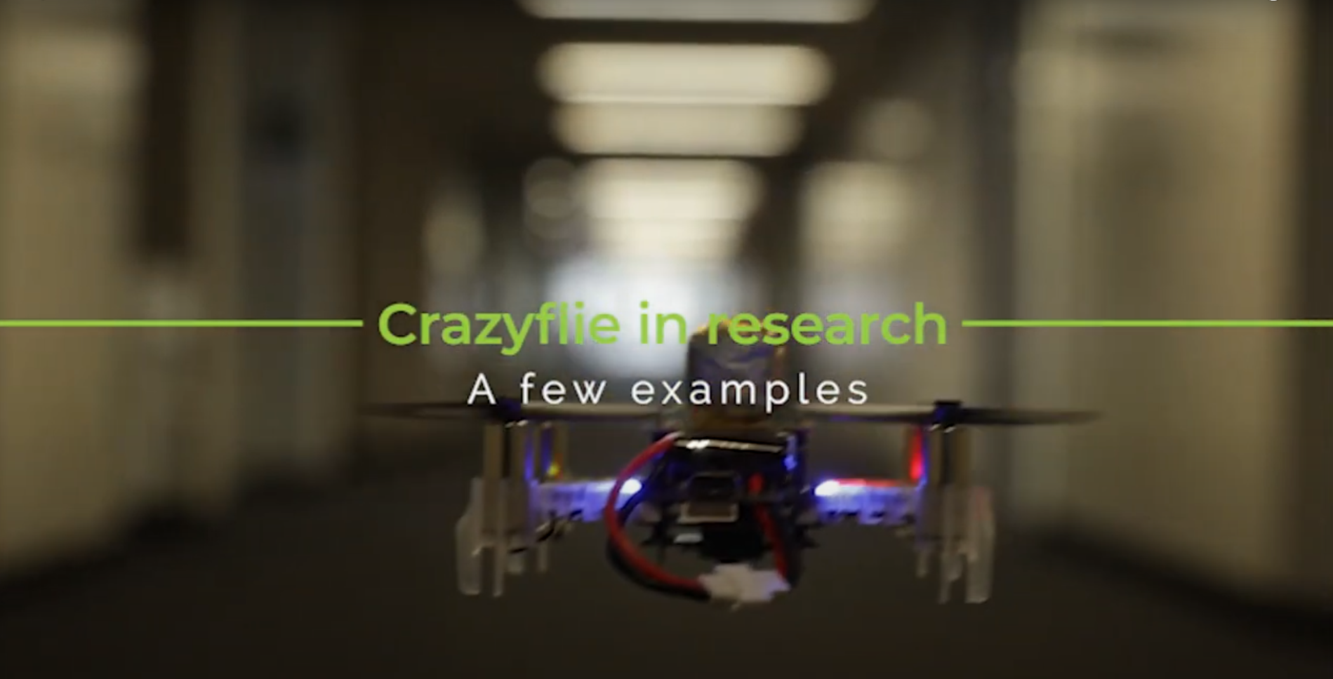
It’s now become a tradition to create a video compilation showcasing the most visually stunning research projects that feature the Crazyflie. Since our last update, so many incredible things have happened that we felt it was high time to share a fresh collection.
As always, the toughest part of creating these videos is selecting which projects to highlight. There are so many fantastic Crazyflie videos out there that if we included them all, the final compilation would last for hours! If you’re interested, you can find a more extensive list of our products used in research here.
The video covers 2023 and 2024 so far. We were once again amazed by the incredible things the community has accomplished with the Crazyflie. In the selection, you can see the broad range of research subjects the Crazyflie can be a part of. It has been used in mapping, or swarms – even in heterogeneous swarms! With its small size, it has also been picked for human-robot interaction projects (including our very own Joseph La Delfa showcasing his work). And it’s even been turned into a hopping quadcopter!
Here is a list of all the research that has been included in the video:
Energy efficient perching and takeoff of a miniature rotorcraft Yi-Hsuan Hsiao, Songnan Bai, Yongsen Zhou, Huaiyuan Jia, Runze Ding, Yufeng Chen, Zuankai Wang, Pakpong Chirarattananon City University of Hong Kong, Massachusetts Institute of Technology, The Hong Kong Polytechnic University
But enough talking, the best way to show you everything is to actually watch the video:
A huge thank you to all the researchers we reached out to and who agreed to showcase their work! We’re especially grateful for the incredible footage you shared with us—some of it was new to us, and it truly adds to the richness of the compilation. Your contributions help highlight the fantastic innovations happening within the Crazyflie community. Let’s hope the next compilation also shows projects with the Brushless!