We have some very busy weeks behind us and ahead! As we are working hard on releasing the new CF Brushless, we have been preparing for the upcoming ROSCon in Odense Denmark next week (see this previous blogpost) and we also featured on the latest OpenCV live episode as well! So more about both in this blogpost.
OpenCV Live! Demo Driven Development
We were featured as guests on the latest OpenCV Live! episode hosted by Phil Nelson and Satya Mallick, where we went through a bit of the history of the start of Bitcraze and all of the (crazy) demos done with the Crazyflie in the last decade. We have done a similar topic for our latest developer meeting, but for this episode we put the focus more on vision based demos, since OpenCV has been definitely used in the past at Bitcraze for various reasons! Just type in OpenCV in the top right search barto check out any of the blogs we have written.
During the OpenCV live episode of the 10th of October, Arnaud and Kimberly told the backstories of these demos that went from a manual flight fail where Arnaud flew the Crazyflie 1.0 in Marcus’ hair, using OpenCV and Aruco markers for positioning to flying a swarm in your kitchen. It was really fun to do and alos one lucky listener managed to answer the two questions the host Phil asked at the end, namely “Where does the name Crazyflie come from?” and “Why is the last part (‘-flie’) spelled this way?” and won a STEM ranging bundle. If you’d like to know the answers, go and watch the latest OpenCV! Live episode ;) Enjoy!
ROSCon – What to expect?
So next week we will be present as Silver Sponsor at ROSCon Odense, namely on Monday 21th and Wednesday 23rd of October. The Bitcraze booth will be located on number 21 so that should be near the coffee break place! We will have are old trusty cage with some upgrades with a nice ROS demo which is similar to the one explained in this Crazyflie ROS tutorial we have written a while ago, but then the swarming variant of it. We also hope to show a Brushless Crazyflie Prototype, and a new camera deck prototype, along with anything else we can find lying around at our office :D.
Moreover, Arnaud will be given a presentation on the lighthouse positioning system, namely at Wednesday 23rd of October 14:40 (2:30 pm) called ‘The Lighthouse project: from Virtual Reality to Onboard Positioning for Robotics’. The lighthouse positioning system will also be the system that we will demo at our booth so if you’d like to see it for yourself, or perhaps (during downtime) hack around together with us, you are more than welcome to do so! Check out the Bitcraze ROSCon Eventpage for more details about our demo or the hardware we will show.
It’s now become a tradition to create a video compilation showcasing the most visually stunning research projects that feature the Crazyflie. Since our last update, so many incredible things have happened that we felt it was high time to share a fresh collection.
As always, the toughest part of creating these videos is selecting which projects to highlight. There are so many fantastic Crazyflie videos out there that if we included them all, the final compilation would last for hours! If you’re interested, you can find a more extensive list of our products used in research here.
The video covers 2023 and 2024 so far. We were once again amazed by the incredible things the community has accomplished with the Crazyflie. In the selection, you can see the broad range of research subjects the Crazyflie can be a part of. It has been used in mapping, or swarms – even in heterogeneous swarms! With its small size, it has also been picked for human-robot interaction projects (including our very own Joseph La Delfa showcasing his work). And it’s even been turned into a hopping quadcopter!
Here is a list of all the research that has been included in the video:
Energy efficient perching and takeoff of a miniature rotorcraft Yi-Hsuan Hsiao, Songnan Bai, Yongsen Zhou, Huaiyuan Jia, Runze Ding, Yufeng Chen, Zuankai Wang, Pakpong Chirarattananon City University of Hong Kong, Massachusetts Institute of Technology, The Hong Kong Polytechnic University
But enough talking, the best way to show you everything is to actually watch the video:
A huge thank you to all the researchers we reached out to and who agreed to showcase their work! We’re especially grateful for the incredible footage you shared with us—some of it was new to us, and it truly adds to the richness of the compilation. Your contributions help highlight the fantastic innovations happening within the Crazyflie community. Let’s hope the next compilation also shows projects with the Brushless!
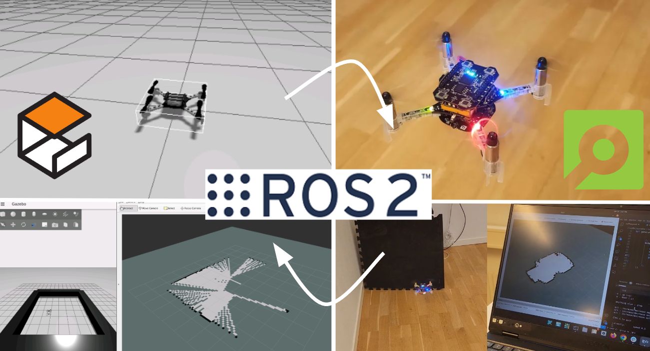
You might remember that at the beginning of this summer, we were invited to do a skill-learning session with the Crazyflie at the Robotics Developer Day 2024 (see this blog post) organized by The Construct. We showed the Crazyflie flying with the multi-ranger deck, capable of mapping the room in both simulation and the real world. Moreover, we demonstrated this with both manual control and autonomous wall-following. Since then, we wanted to make some improvements to the simulation. We now present an updated tutorial on how to do all of this yourself on your own machine.
Note: This tutorial was originally developed for a demonstration at Robotics Developer Day 2024. As the integration depends on specific versions of ROS 2, Gazebo, and related packages, it may require adjustments to work with current software. This post is no longer actively maintained by the Bitcraze team.
This tutorial will focus on using the multi-ranger ROS 2 nodes for both mapping and wall-following in simulation first, before trying it out on the real thing. You will be able to tune settings to your specific environment in simulation first and then use exactly the same nodes in the real world. That is one of the main strengths of ROS, providing you with that flexibility.
We have made a video of what to expect of the tutorial, for which you should use this blogpost for the more detailed instructions.
Watch this video first and then again with the instructions below
What do you need first?
You’ll need to setup some things first on the PC and acquire hardware to follow this tutorial in full:
Gazebo Harmonic – Install via these instructions This is not the recommended Gazebo for humble but we will install the specific ROS bridge for this later. Just make sure that you don’t have gazebo classic installed on your machine.
Hardware
You’ll need to components at least of the STEM ranging bundle
If you have any different setup of your computer or positioning system, it is okay as the demos should be simple enough to work, but, be prepared for some warning/error handling that this tutorial might have not covered.
Time to complete:
This is an approximation of how much time you need to complete this tutorial, depended on your skill level, but if you already have experience with both ROS 2/Gazebo and the Crazyflie it should take 1 hour.
If you have the Crazyflie for the first time, it would probably be a good idea to go through the getting started tutorial and connect to it with a CFclient with the Flowdeck and Multi-ranger deck attached as a sanity check if everything is working before jumping into ROS 2 and Gazebo.
Go to the ros2_ws workspace and build the packages
cd ~/crazyflie_mapping_demo/ros2_ws/
source /opt/ros/humble/setup.bash
colcon build --cmake-args -DBUILD_TESTING=ONCode language:JavaScript(javascript)
Building will take a few minutes. Especially Crazyswarm2 will show a lot of warnings and std_err, but unless the package build has ‘failed’, just ignore it for now until we have proposed a fix to that repository.
If the build of all the packages passes and non failed, please continue to the next step!
2. Simple mapping simulation
This section will explain how to create a simple 2D map of your environment using the multi-ranger. The ROS 2 package designed for this is specifically made for the multi-ranger, but it should be compatible with NAV2 if you’d like. However, for now, we’ll focus on a simple version without any localization inferred from the map.
Open up a terminal which needs to be sourced for both the gazebo model and the newly build ROS 2 packages:
If you get a ‘No such file or directory’ error on the model, try entering the full path in GZ_SIM_RESOURCE_PATH export.
Gazebo will start with the Crazyflie in the center. You can get a close-up of the Crazyflie by right-clicking it in the Entity tree and pressing ‘Move to’. You can also choose to follow it, but the camera tracking feature of Gazebo needs some tuning to track something as small as the Crazyflie. Additionally, you will see RVIZ starting with the map view and transforms preconfigured.
Open up another terminal, source the installed ROS 2 distro and open up the ROS 2 teleop keyboard node:
source /opt/ros/humble/setup.bash
ros2 run teleop_twist_keyboard teleop_twist_keyboard
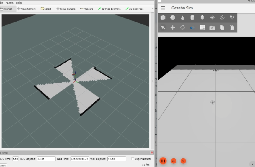
Have the Crazyflie take off with ‘t’ on your keyboard, and rotate it around with the teleop instructions. In RVIZ you should see the map being created and the transform of the Crazyflie moving. You should be able to see this picture, and in this part of the video.
Screenshot of the Crazyflie in Gazebo generating a map with Teleop (video)
3. Simple mapping real world
Now that you got the gist of it, let’s move to the real Crazyflie!
First, if you have a different URI of the Crazyflie to connect to, first change the config file ‘crazyflie_real_crazyswarm2.yaml’ in the crazyflie_ros2_repository. This is a file that Crazyswarm2 uses to know to which Crazyflie to connect to.
Open up the config file in gedit or your favorite IDE like visual code:
and change the URI on this line specifically to the URI of your Crazyflie if necessary. Mind that you need to rebuild ros2_ws again to make sure that this has an effect.
Now source the terminal with the installed ROS 2 packages and the Gazebo model, and launch the ROS launch of the simple mapper example for the real world Crazyflie.
Now open up another terminal, source ROS 2 and open up teleop:
source /opt/ros/humble/setup.bash
ros2 run teleop_twist_keyboard teleop_twist_keyboard
Same thing, have the Crazyflie take off with ‘t’, and control it with the instructions.
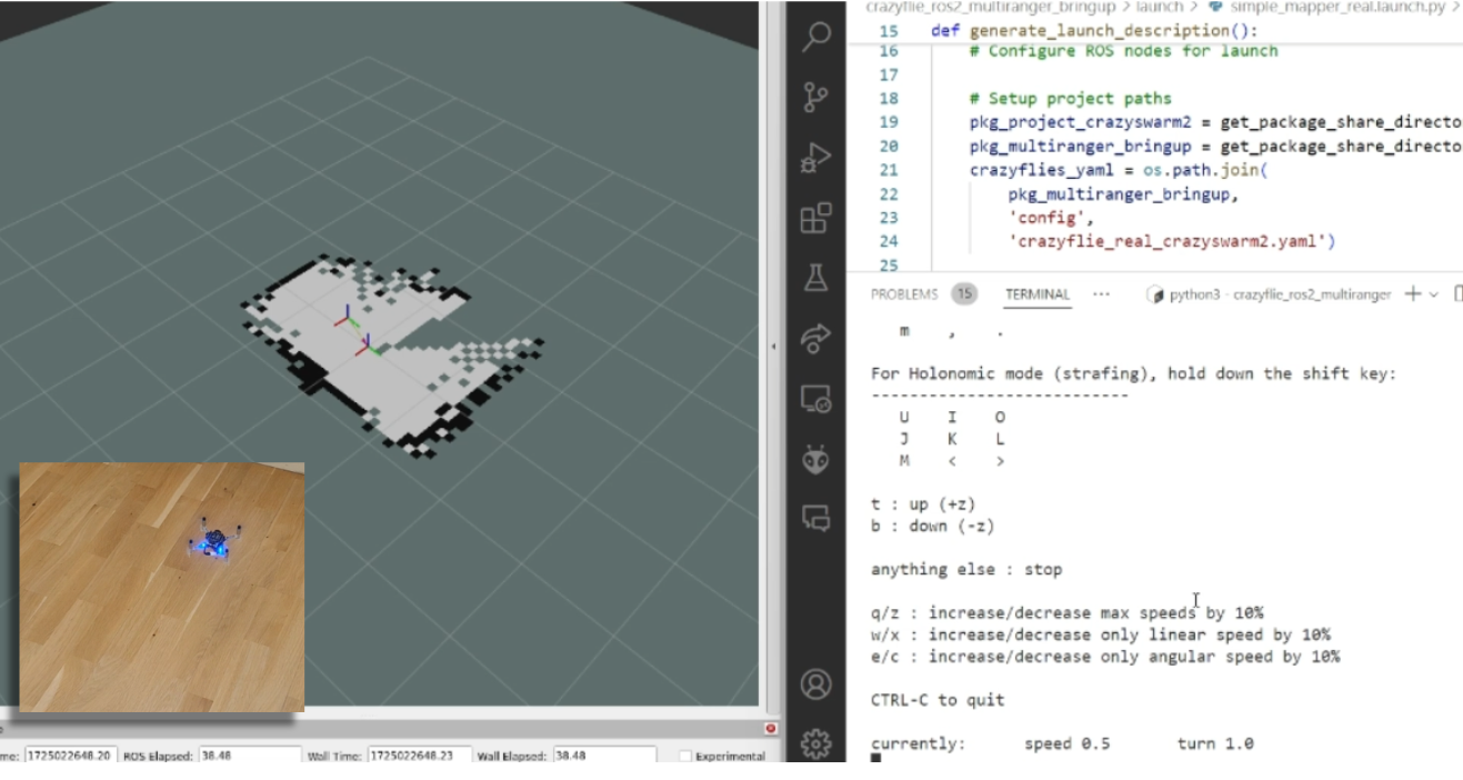
You should be able to see this on your screen, which you can also check with this part of the video.
Screen shot of the real Crazyflie mapping while being controlled with ROS 2 teleop (video)
Make the Crazyflie land again with ‘b’, and now you can close the ROS 2 node in the launch terminal with ctrl + c.
4. Wall following simulation
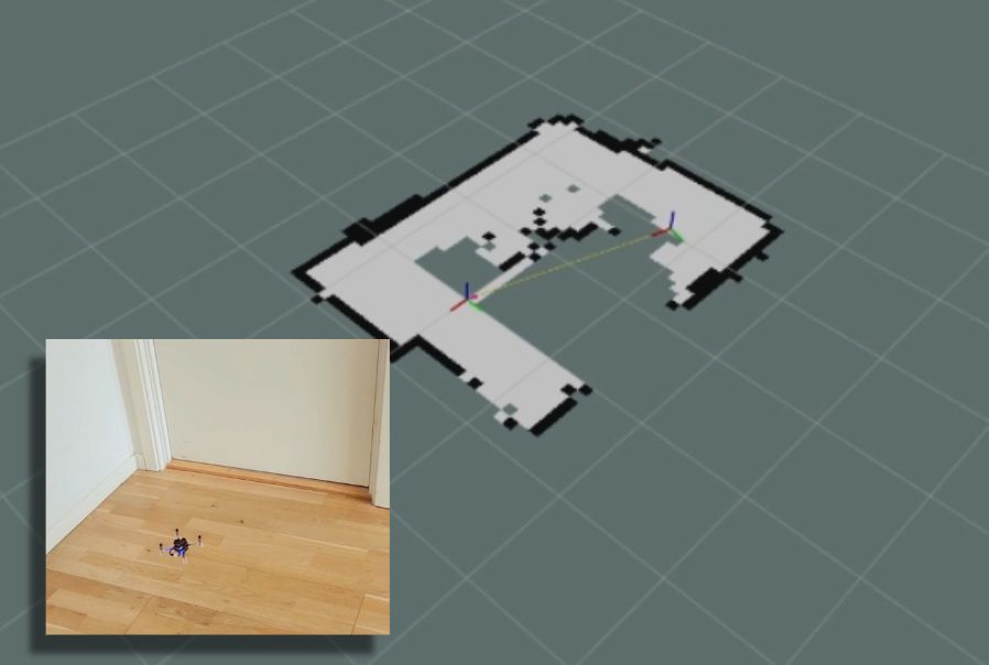
Previously, you needed to control the Crazyflie yourself to create the map, but what if you could let the Crazyflie do it on its own? The `crazyflie_ros2_multiranger` package includes a `crazyflie_ros2_multiranger_wall_following` node that uses laser ranges from the multi-ranger to perform autonomous wall-following. Then, you can just sit back and relax while the map is created for you!
Let’s first try it in simulation, so open up a terminal and source it if you haven’t already (see section of the Simple mapper simulation). Then launch the wall follower ROS 2 launch file:
Take off and wall following will go fully automatic. The simulated Crazyflie in Gazebo will fly forward, stop when it sees a wall with it’s forward range sensor and follow the wall on its left-hand side.
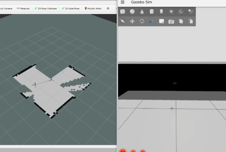
You’ll see on RVIZ2 when the full map is created like here below and this part of the tutorial video.
Screenshot of the simulated Crazyflie in Gazebo mapping will autonomously wall following (video)
You can stop the simulated Crazyflie by the following service call in another terminal that is sourced with ROS 2 humble.
ros2 service call /crazyflie/stop_wall_following std_srvs/srv/Trigger
The simulated Crazyflie will stop wall following and land. You can also just close the simulation, since nothing can happen here.
5. Wall following real world
Now that we have demonstrated that the wall-following works in simulation, we feel confident enough to try it in the real world this time! Make sure you have a fully charged battery, place the Crazyflie on the floor facing the direction you’d like the positive x-axis to be (which is also where it will fly first), and turn it on.
Make sure that you are flying with a room with clear defined walls and corners, or make something with cardboard such as a mini maze, but the current algorithm is optimized to just fly in a squarish room.
Source the ROS 2 workspace like previously and start up the wall follower launch file for the
Like the simulated Crazyflie, the real Crazyflie will take off automatically and automatically do wall following, so it is important that it is flying towards a wall. It should look like this screenshot, or you can check it with this part of the video.
The real crazyflie wall following autonomously while mapping the room (video).
Be careful here to not accidently run this script with the Crazyflie sitting on your desk!
If you’d like the Crazyflie to stop, don’t stop theROS2 nodes with ctrl-c, since it will continue flying until crash. It’s not like simulation unfortunately where you can close the environment and nothing will happen. Instead, use the ROS 2 service made for this in a different terminal:
ros2 service call /crazyflie_real/stop_wall_following std_srvs/srv/Trigger
Similar the real Crazyflie will stop wall following and land. Now you can close the ROS 2 terminals and turn off the crazyflie.
Next steps?
We don’t have any more demos to show but we can give you a list of suggestions of what you could try next! You could for instance have multiple Crazyflies mapping together like in the video shown here:
This uses the mapMergeForMultiRobotMapping-ROS2 external project, which is combined with Crazyswarm2 with this launch file gist. Just keep in mind that, currently, it would be better to use a global positioning system here, such as the Lighthouse positioning system used in the video. Also, if you’d like to try this out in simulation, you’ll need to ensure different namespaces for the Crazyflies, which the current simulation setup may not fully support.
Another idea is to connect the NAV2 stack instead of the simple mapper. There exists a couple of instructions on the Crazyswarm2 ROS2 tutorials so you can use those as reference. Check out the video below here.
Moreover, if you are having difficulties setting up your computer, I’d like to remind you that the skill-learning session we conducted for Robotics Developer Day was entirely done using a ROSject provided by The Construct, which also allows direct connection with the Crazyflie. The only requirement is that you can run Crazyswarm2 on your local machine, but that should be feasible. See the video of the original Robotics Developer Day skill-learning session here:
The last thing to know is that the ROS 2 nodes in this tutorial are running ‘offboard,’ so not on the Crazyflies themselves. However, do check out the Micro-ROS examples for the Crazyflie by Eprosima whenever you have the time and would like to challenge yourself with embedded development.
A few weeks ago, the prestigious Robotics: Science and Systems (RSS) conference was held at Delft University of Technology. We helped with the co-organization of a half-day tutorial and workshop called “Aerial Swarm Tools and Applications” so Kimberly (I) was there on behalf of both Bitcraze and Crazyswarm2. In this blog post, we will tell you a bit about the conference itself and the workshop (and perhaps also a tiny bit about RoboCup)
The Robotics: Science and Systems conference
The Robotics: Science and Systems conference, also known as RSS, is considered one of the most important robotics conferences to attend, alongside ICRA and IROS. It distinguishes itself by having only a single track of presented papers, which makes it possible for all attendees to listen to and learn about all the cool robotics work done in a wide range of fields. It also makes it more difficult to get a paper accepted due to the fixed number of papers they can accept, so you know that whatever gets presented is of high quality.
This year the topic was very much on large language models (LLMs) and their application in robotics, most commonly manipulators. Many researchers are exploring the ways that LLMs could be used for robotics, but that means not a lot of small and embedded systems were represented in these papers. We did find one paper where Crazyflies were presented, namely the awesome work by Darrick et al. (2024) called ‘Stein Variational Ergodic Search’ which used optimal control for path planning to achieve the best coverage.
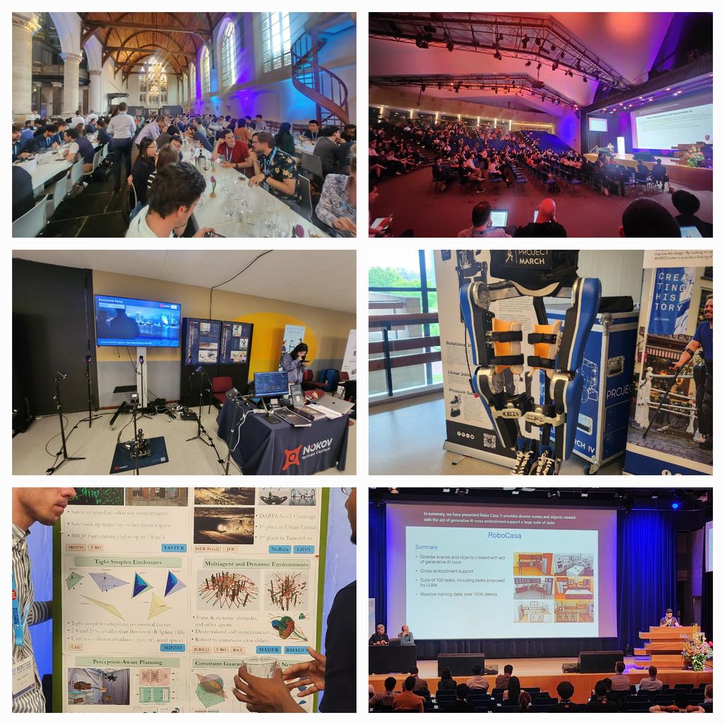
It gave us the chance to experience many of the other works that could be found at RSS. One in particular was about the robotic design of the cute little biped from Disney Imagineering named “Design and Control of a Bipedal Robotic Character” by Grandia et al. (2024). Also very impressive was the Agile flight demo by the group of Davide Scaramuzza, and we enjoyed listening to the keynote by Dieter Fox, senior director at Nvidia, talking about ‘Where is RobotGPT?’. The banquet location was also very special, as it was located right in the old church of Delft.
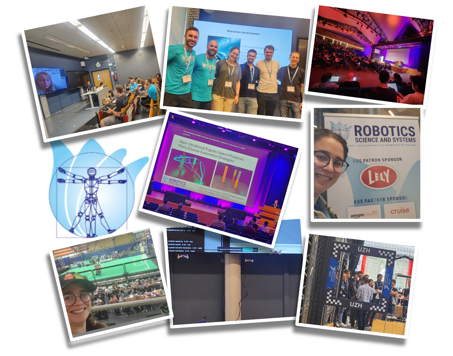
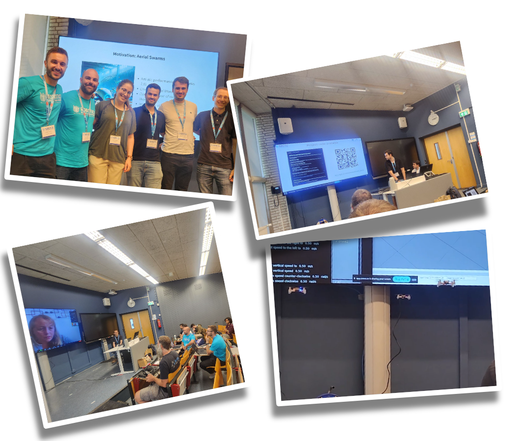
The main reason we joined RSS was that we were co-organizing the workshop ‘Aerial Swarm Tools and Applications’. This was done in collaboration with Wolfgang Hönig from Crazyswarm2/TU Berlin, Miguel Fernandez Cortizas and Rafel Perez Segui from Aerostack2/Polytechnic University of Madrid (UPM), and Andrea Testa, Lorenzo Pichierri, and Giuseppe Notarstefano from CrazyChoir/University of Bologna. The workshop was a bit of a hybrid as it contained both talks on various aerial swarm applications and tutorials on the different aerial swarm tools that the committee members were representatives of.
Photos of the Aerial Swarm Tools and Applications workshop
Sabine Hauert from the University of Bristol started off the workshop by talking about “Trustworthy swarms for large-scale environmental monitoring.” Gábor Vásárhelyi from Collmot Robotics and Eötvös University gave a talk/tutorial about Skybrush, showing its suitability not only for drone shows but also for research (Skybrush was used for the Big Loco Test show demo we did 1.5 years ago). The third speaker was SiQi Zhou, speaking on behalf of Angela Schöllig from TU Munich, discussing “Safe Decision-Making for Aerial Swarms – From Reliable Localization to Efficient Coordination.” Martin Saska concluded the workshop with his talk “Onboard relative localization for agile aerial swarming in the wild” about their work at the Czech TU in Prague. They also organize the Multi-robot systems summer school every year, so if you missed it this year, make sure to mark it in your calendar for next summer!
We had four tutorials in the middle of the workshop as well. Gábor also showed Skybrush in simulation after his talk for participants to try out. Additionally, we had tutorials that included real, flying Crazyflies live inside the workshop room! It was a bit of a challenge to set up due to the size of the room we were given, but with the lighthouse system it all worked out! Miguel and Rafael from Aerostack2 were first up, showing a leader-follower demo. Next up were Wolfgang and Kimberly (Crazyswarm2) who showed three Crazyflies collaboratively mapping the room, and finally, Andrea and Lorenzo from CrazyChoir demoed formation control in flight.
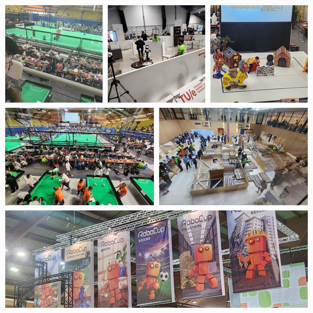
Luckily, there was also a bit of time to visit Eindhoven for a field trip to the 2024 edition of the world championship competitions of RoboCup! This is a very large robotics competition held in several different divisions, namely Soccer (with many subdivisions), Industrial, Rescue, @Home, and Junior. Each country usually has its own national championships, and those that win there can compete in the big leagues at events like these. RoboCup was extremely fun to attend, so if any robotics enthusiasts happen to live close to one of these, go! It’s awesome.
Photos of the field trip to RoboCup
Maybe drone competitions might be one of RoboCup’s divisions in the future :)
Whenever we show the Crazyflie at our booth at various robotics conferences (like the recent ICRA Yokohama), we sometimes get comments like ‘ahh that’s cute’ or ‘that’s a fun toy!’. Those who have been working with it for their research know differently, but it seems that the general robotics crowd needs a little bit more… convincing! Disregarding its size, the Crazyflie is a great tool that enables users to do many awesome things in various areas of robotics, such as swarm robotics and autonomy, for both research and education.
We will be showing that off by giving a live tutorial and demonstration at the Robotics Developer Day 2024, which is organized by The Construct and will take place this Friday, 5th of July. We have a discount code for you to use if you want to get a ticket; scroll down for details. The code can be used until 12 am midnight (CEST) on the 2nd of July.
The Construct and Robotics Developer Day 2024
So a bit of background information: The Construct is an online platform that offers various courses and curriculums to teach robotics and ROS to their users. Along with that, they also organize all kinds of live training sessions and events like the Robotics Developer Day and the ROS Awards. Unfortunately, the deadline for voting in the latter has passed, but hopefully in the future, the Crazyflie might get an award of its own!
What stands out about the platform is its implementation of web-based virtual machines, called ‘ROSJects,’ where ROS and everything needed for it is already set up from the start. Anyone who has worked with ROS(2) before knows that it can be a pain to switch between different versions of ROS and Gazebo, so this feature allows users to keep those projects separate. For the ROS Developer Day, there will be about five live skill-learning sessions where a ROSject is already preconfigured and set up for the attendees, enabling them to try the tutorial simultaneously as the teacher or speaker explains the framework.
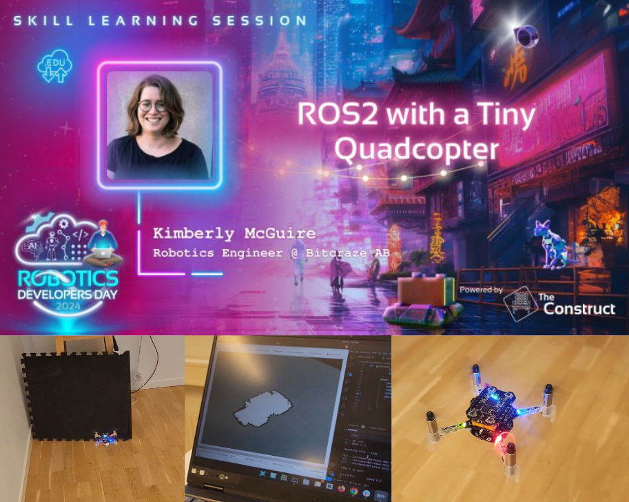
Skill learning session with the Crazyflie
One of the earlier mentioned skill learning sessions is, of course, one with the Crazyflie! The title is “ROS 2 with a Tiny Quadcopter,” and it is currently planned to be the first skill learning session of the event, scheduled at 15:15 (3:15 pm) CEST. The talk will emphasize the use of simulation in the development process with aerial robotics and iterating between the real platform and the simulated one. We will demonstrate this with a Crazyflie 2.1 equipped with a Lighthouse deck and a Multi-ranger deck. Moreover, it will also use a Qi-charging deck on a charging platform while it patiently waits for its turn :D
What we will be showing is a simple implementation of a mapping algorithm made specifically for the Crazyflie’s Multiranger deck, which we have demonstrated before at ROSCon Kyoto and in the Crazyswarm2 tutorials. What is especially different this time is that we are using Gazebo for the simulation parts, which required some skill learning on our side as we have been used to Webots over the last couple of years (see our tutorial for that). You can find the files for the simulation part in this repository, but we do advise you to follow the session first.
You can, if you want, follow along with the tutorial using a Crazyflie yourself. If you have a Crazyflie, Crazyradio, and a positioning deck (preferably Lighthouse positioning, but a Flowdeck would work as well), you can try out the real-platform part of this tutorial. You will need to install Crazyswarm2 on a separate Ubuntu machine and add a robot in your ROSject as preparation. However, this is entirely optional, and it might distract you from the cool demos we are planning to show, so perhaps you can try this as a recap after the actual skill learning session ;).
Here is a teaser of what the final stage of the tutorial will look like:
Win a lighthouse explorer bundle and a Hands-On Pass discount
We are also sponsors of the event and have agreed with The Construct to award one of the participants a Crazyflie if they win any contest. Specifically, we will be awarding a Lighthouse Explorer bundle, with a Qi deck and a custom-made charging pad similar to the ones we show at fairs like ICRA this year. So make sure to participate in the contests during the day for a chance to win this or any of the other prizes they have!
It is possible to follow the event for free, but if you’d like to participate with the ROSjects, you’ll need to get a hands-on pass. If you haven’t yet gotten a hands-on ticket for the Robotics Developer Day, please use our 50% off discount code:
On a side note, we will be at the Robotics: Science and Systems Conference in Delft from July 15th to 19th, 2024—just about two weeks from now. We won’t have a booth as we usually do, but we will be co-organizing a half-day workshop titled Aerial Swarm Tools and Applications (more details on this website).
We will be organizing this workshop together with our collaborators at Crazyswarm2, as well as the developers of CrazyChoir and Aerostack2. We’re excited to showcase demos of these frameworks with a bunch of actual Crazyflies during the workshop, if the demo gods are on our side :D. We will also have great speakers, including: SiQi Zhou (TU Munich), Martin Saska (Czech Technical University), Sabine Hauert (University of Bristol), and Gábor Vásárhelyi (Collmot/Eötvös University).
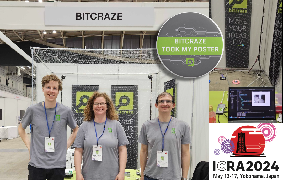
“What? You are in Japan? Again!?”. Yup that is right! We loved IROS Kyoto 2022 so much that we just couldn’t wait to come back again. Barbara, Arnaud and Rik are setting up the booth as we speak to show some Bitcraze awesomeness to you! Come and say hi at booth IC085.
The gang before the rush starts!
Crazyflie Brushless and Camera expansion
Of all the prototypes we are the most excited of showing you the Crazyflie Brushless and the ‘forward facing expansion connector prototype’ aka the Camera deck. Here you can see them both in action at a tryout of our demo. We have also written blogposts about both so make sure to read them as well (Brushless blogpost, Camera expansion blogpost)
The Crazyflie Brushless flying with a Camera deck.
Also we will explain about the contact charging prototype (see the blogpost here) and will be showing all of our decks at the booth as well. And of course our fully autonomous, onboard, decentralized peer-to-peer and avoiding swarm demo will be displayed as always. Make sure to read this blogpost of when we showed this demo at IROS 2022 to understand what is fully going on!
We will be providing a ‘special disposal service’ for your conference poster! We would love to see what you are working on and get your poster, because we have a lot of space in our updated office/flight space but a lot of empty walls.
If you hand in your poster at the booth, you’ll get a special, one-of-a-kind, button badge that you can wear proudly during the conference! So we will see you at booth IC085!
It’s not often a blog post happens on the 25th of December, so this time, you’re having a treat with some new Bitcraze prototypes as a present from us! If you have time to get away from the Christmas table, there’s something we’d love you to watch:
Now let’s try to see if you noticed all the new stuff you see in this video!
Our new flight lab
We teased it, but in the beginning of December, we got our extended flight lab! We added 110 m2 to our flight space. It was a rush to have everything ready for the video – we cleaned everything, painted the walls and the green logo, set up the positioning system without our truss… But now we’re happy to show you how big the space is! Even if it’s hard to convey the real size on camera.
The Crazyflie 2.1 brushless
We already talked about it in this blog post, but the brushless has made significant progress and we feel confident that you will get your hands on it in 2024. Here, we use the extra power for a fast and agile flight. It also was very stable and didn’t crash once during the shooting!
The Lighthouse V2
Yes, you counted right! The Brushless flew with 16 base stations! We’ve worked really hard this past three months to create a new Lighthouse deck – the Lighthouse deck 2.0. It could get its position from 16 base stations. That’s 4 times more than what was previously possible! It behaved consistently well during the different tries, and we are really happy with the result. Right now, it’s just a prototype, but we’re hoping to get it to the next step in the coming months.
The contact charging station
Marcus created a power charger for the Brushless that doesn’t need any extra deck to allow for charging. It connects with the brushless feet. It has also the cool feature of changing LEDs indicating the status (idle, charging or charged). It is also a prototype, and we don’t know if this will end up being a product
The high-power LED
This is trickier to see, but it’s not our usual LED ring that the brushless carries. It’s a new, powerful LED underneath. It is so powerful that it nearly blinded us when we tried it for the first time. We put a diffuser on it, and it allowed the Crazyflie to be visible at such a high pace! This is a prototype too of course and we’re not sure if we will release it, but it’s fun to use for this kind of project.
Other announcements
During this week, our office is closed- we take this week to celebrate and rest a little before 2024. This means that shipping and support will be greatly reduced.
But we’re back the week after- at a somewhat reduced pace though. The developer meeting on the 3rd of January is maintained but without any presentation. We’ll take this time to answer any questions you have and talk a little! The details are here.
Bitcraze got their presents this year: a handful of working prototypes! We hope we got your wishes too, merry Christmas to you!
The Flow deck has been around for some time already, officially released in 2017 (see this blog post), and the Flow deck v2 was released in 2018 with an improved range sensor. Compared to MoCap positioning and the Loco Positioning System (based on Ultrawideband) that were already possible before, optical flow-based positioning for the Crazyflie opened up many more possibilities. Flight was no longer confined to lab environments with set-up external systems; people could bring the Crazyflie home and do their hacking there. Moreover, doing research for exploration techniques that cannot rely on external positioning systems was possible with it as well. For example, back in my day as a PhD student, I relied heavily on the Flow deck for multi-Crazyflie autonomous exploration. This would have been very difficult without it.
However, despite the numerous benefits that the Flow deck provides, there are also several limitations. These limitations may not be immediately familiar to many before purchasing a Crazyflie with a Flow deck. A while ago, we wrote a blog post about positioning systems in general and even delved into the Loco Positioning System in detail. In this blog post, we will explore the theory of how the Flow deck enables the Crazyflie to fly, share general tips and tricks for ensuring stable flight, and highlight what to avoid. Moreover, we aim to make the Flow deck the focus of next week’s Developer meeting, with the goal of improving or clarifying its performance further.
Theory of the Flow deck
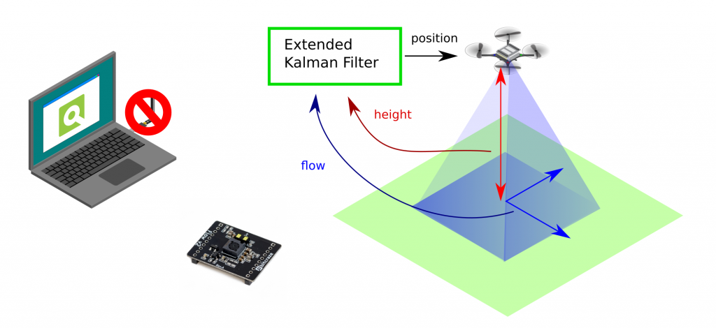
I won’t delve into too much detail but will provide a generic indication of how the Flow deck works. As previously explained in the positioning system blog post, the Flow deck is a relative positioning system with onboard estimation. “Relative” means that wherever you start is the (0, 0, 0) position. The extended Kalman filter processes flow and height information to determine velocity, which is then integrated to estimate the position—essentially dead reckoning. The onboard Kalman filter manages this process, enabling the Crazyflie to use the information for stable hovering.
The optical flow sensor (PMW3901) calculates pixel flow per frame (this old blog post explains it well), and the IR range sensor (VL53L1x) measures height up to 4 meters (under ideal conditions). The Kalman filter incorporates a measurement model that describes the relationship between these two values and the velocity of the Crazyflie. More detailed information can be found in the state estimation documentation. This capability allows the Crazyflie to hover, as explained in the getting started tutorial.
If you want to fly with the Crazyflie and the Flow deck, there are a couple of things to take in mind:
Take off from a floor with texture. Natural texture like wood flooring is probably the best.
The floor shouldn’t be too shiny, and be aware of infrared scattering for the height sensor
The room should be well-lit, as the sensor needs to see the texture.
There are certain situations that the Flow deck has some issues with:
Low or no texture. Flying above something that is only one plain color
Black areas. Similar reason to flying above no texture, but it’s more difficult than usual. Especially with startup, the position estimate diverges
Low light conditions
Flying over its own shadow
We made a video that shows these types of behaviors, starting of course with the most ideal flying conditions:
Moreover, it is also important to note that you shouldn’t fly too high or yaw too often. The latter will make the Crazyflie drift, as the optical flow cannot be distinguished as being caused by the yaw movement.
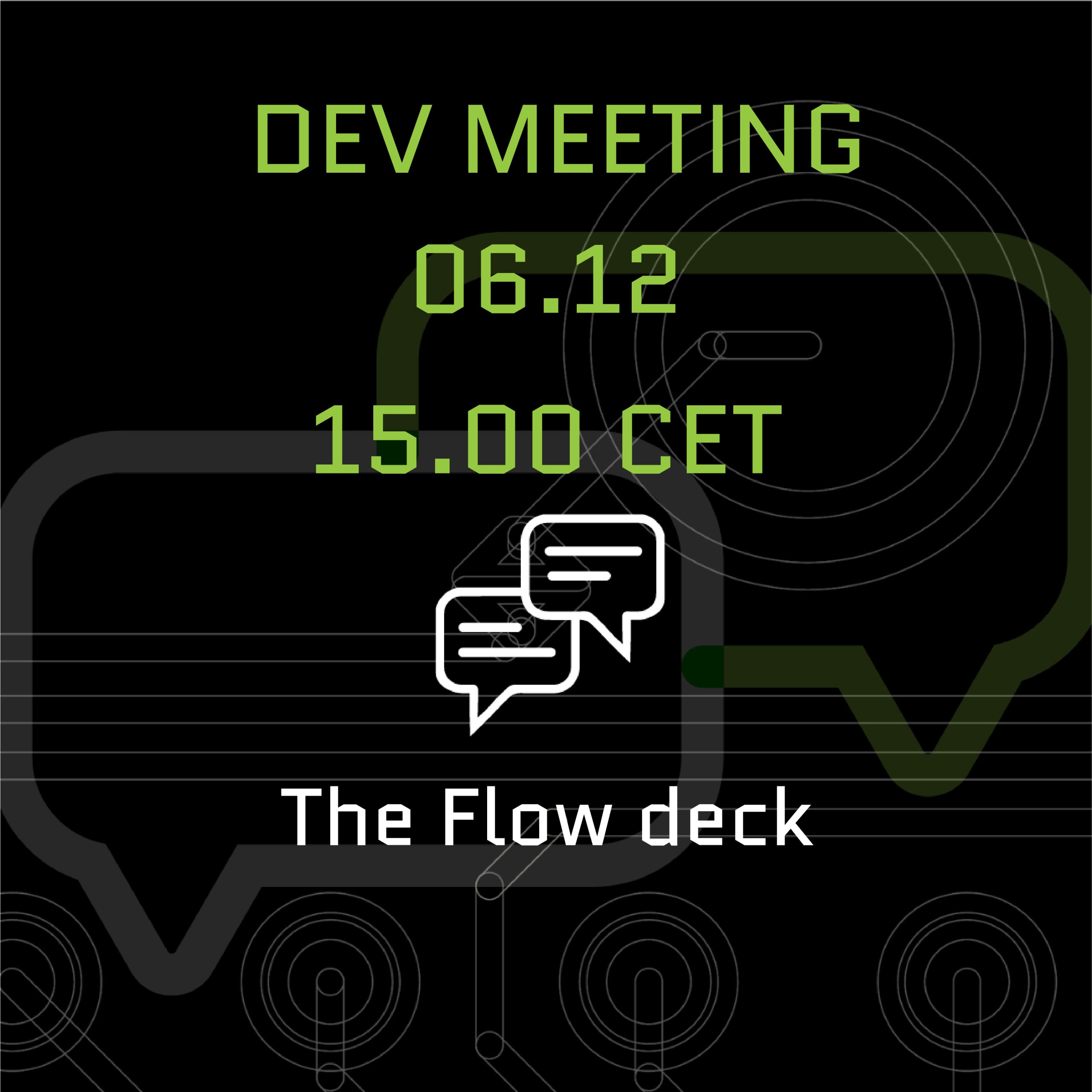
Developer meeting about Flow deck
We believe that many of the issues people experience are primarily due to the invisibility of the positioning quality. In many of our examples, the Crazyflie will not take off if the position is stable. However, we don’t have a corresponding functionality in our CFclient, as it is more up to the user to recognize when the positioning is diverging. There is a lot of room for improvement in this regard.
This is the reason why the next developer meeting will specifically focus on the Flow deck, which will be on Wednesday the 6th of December, 3 pm central European time. During the meeting, we will explain more about the Flow deck, discuss the issues we are facing, and explore ways to enhance the visibility of positioning quality. Check out this discussion thread for information on how to join.
Today, we welcome Dimitrios Chaikalis from New York University to talk about their project of cooperative flight. Enjoy!
For our work in cooperative flight, we developed controllers for many tightly coupled drones to fly as a unit. The idea is that, either in a centralized or decentralized manner, it should be possible to treat drones as thrust force and yaw moment modules, in order to allow many small drones to carry objects too heavy for a single one to lift.
It quickly turned out that the Crazyflies, with their small size, open-source firmware, ROS compatibility, and, as we happily found out after hours upon hours of crashes, amazing durability, would be the perfect platform to test our controllers.
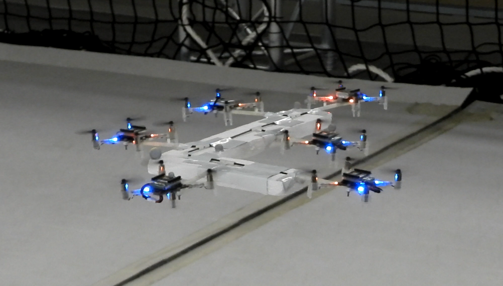
We designed and 3D-printed very lightweight, hollow connecting rods that could latch onto Crazyflies on one side, along with a number of lightweight polygons such as squares and hexagons with housings for the other side of the rods on all their faces. This allowed us to seamlessly change between geometric configurations and test our controllers.
We first tested with some symmetric triangle and quad formations.
The above is probably literally the first time our cooperative configuration achieved full position control
The tests on quad-copter configurations started as we transitioned to fully modular designs
Eventually, to make the controller generic, we developed a simple script that could deduce with some accuracy the placement of drones given a small lexicographic description submitted by the tester as a string, essentially denoting a sequence of rods and polygons utilized in the current configuration. Of course, some parameters such as rod lengths, or additional weights that we added to the system (such as a piece of foam attached to the structure), could not be known in advance, but the adaptive controller design ensured that the overall system could still achieve stable flight.
Strangely, the L shape has become a sort of ‘staple’ configuration in cooperative load transportation
We also proved that with more than 3 drones in a configuration, we could optimize the thrusts of the agents such that additional performance criteria could be met. For example, in an asymmetric configuration of 5 drones, one of them had a significantly more depleted battery. Crazyflies provide real-time battery voltage feedback, so we were able to use that in an optimization node running in Matlab on a ground computer, choosing thrust levels such that the depleted agent could be utilized less. This was a significant help, because in many of those experiments, the Crazyflies had to operate at more than 80% of their thrust capacity, so battery life optimization was of the essence.
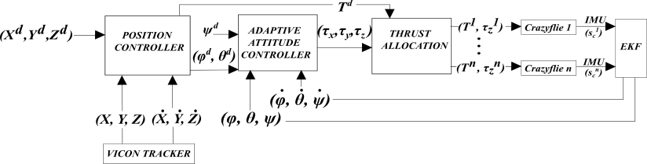
We used ROS for all the code written for the above implementations, using the Crazyflie-ROS package in order to get battery and IMU readings from all drones and provide thrust and roll, pitch, and yaw rate commands at up to 100Hz.
In case you want to build on our work, you can cite the above paper as such:
D. Chaikalis, N. Evangeliou, A. Tzes, F. Khorrami, ‘Modular Multi-Copter Structure Control for Cooperative Aerial Cargo Transportation‘, Journal of Intelligent & Robotic Systems, 108(2), 31.
Today, Vivek Adajania from Learning Systems and Robotics lab write about a project for a safe motion planning of Crazyflie swarm that was published at ICRA 2023. Enjoy!
Motivation
Quadrotor swarms offer significant potential in applications like search and rescue, environmental mapping, and payload transport due to their flexibility and robustness compared to single quadrotors. The core challenge in these applications is collision-free and kinematically feasible trajectory planning. As the quadrotors share space, they must safely manoeuvre around each other and avoid collisions with static obstacles. Existing solutions [1] [2], while effective for generating collision-free trajectories, often struggle in densely cluttered scenarios due to simplifying approximations.
Background
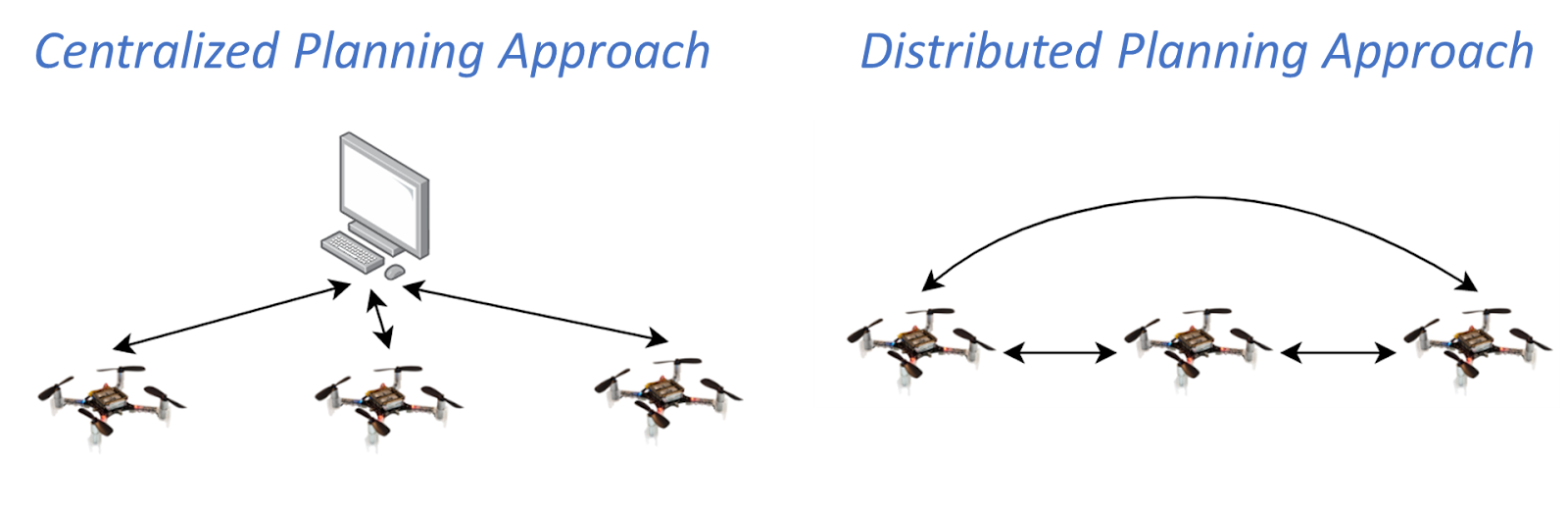
There are two literature groups in the domain of optimization-based quadrotor swarm motion planning: centralized and distributed approaches. In a centralized setup, a central computer solves a joint optimization problem that computes trajectories for all quadrotors at once. These approaches have broad solution space but quickly become computationally intractable as the number of quadrotors increases. On the other hand, the distributed approach involves each quadrotor independently solving its optimization problem and incorporating trajectories shared by the neighbouring quadrotors. This strategy offers improved scalability, yet existing distributed approaches struggle in cluttered environments.
Fig. Centralized and distributed planning approach to quadrotor swarm motion planning. The arrows indicate the flow of communication.
In this work, we adopt a distributed planning strategy. The independent optimization problem that needs to be solved by each of the quadrotors in the distributed setup is a non-convex quadratically constrained quadratic program (QCQP). This nature of the problem stems from non-convex and quadratic collision avoidance constraints and kinematic constraints.
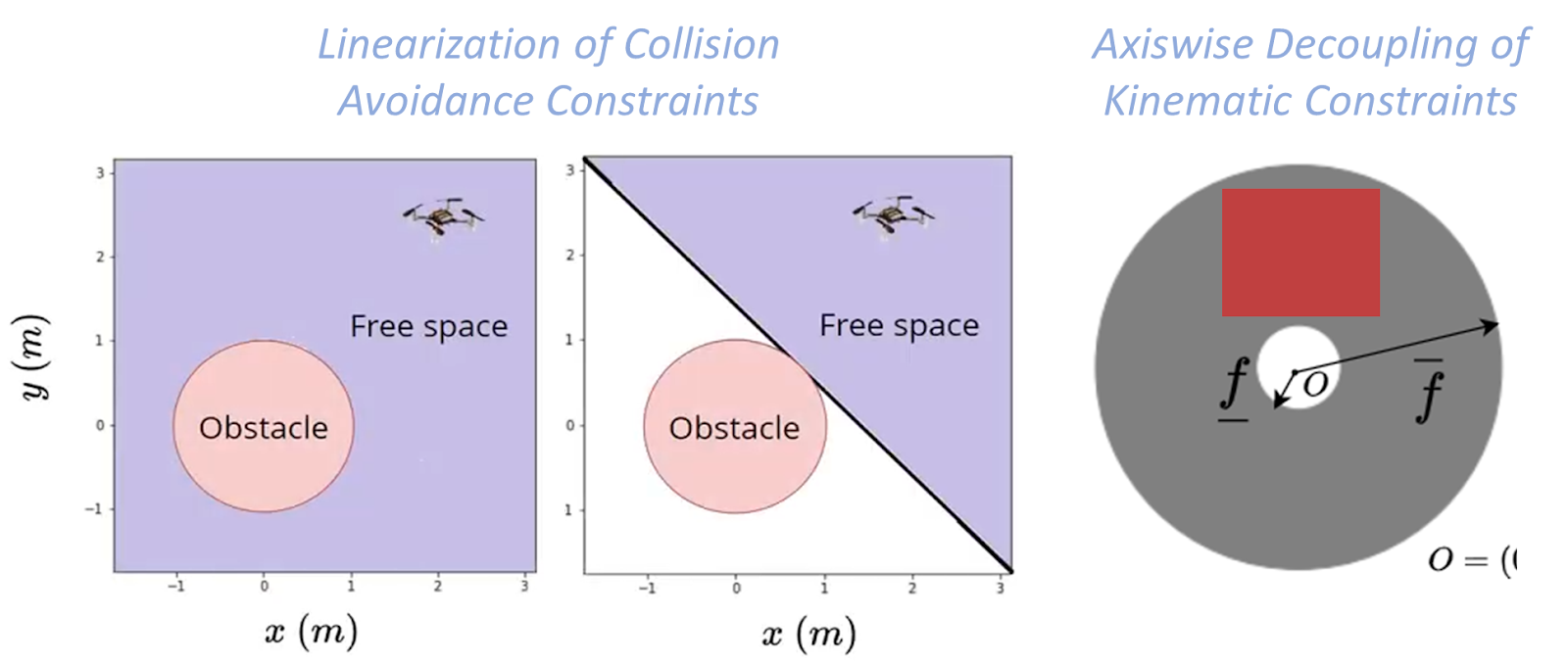
Existing distributed approaches rely on sequential convex programming (SCP) that performs conservative approximations to obtain a quadratic program (QP). First, linearization of the collision avoidance constraints to obtain affine hyperplane constraints. Second, axis-wise decoupling of the kinematic constraints to obtain affine box constraints. We obtain a QP but with small feasible sets.
Fig. Conservative approximations made by Sequential Convex Programming (SCP) based approaches.
Proposed Approach
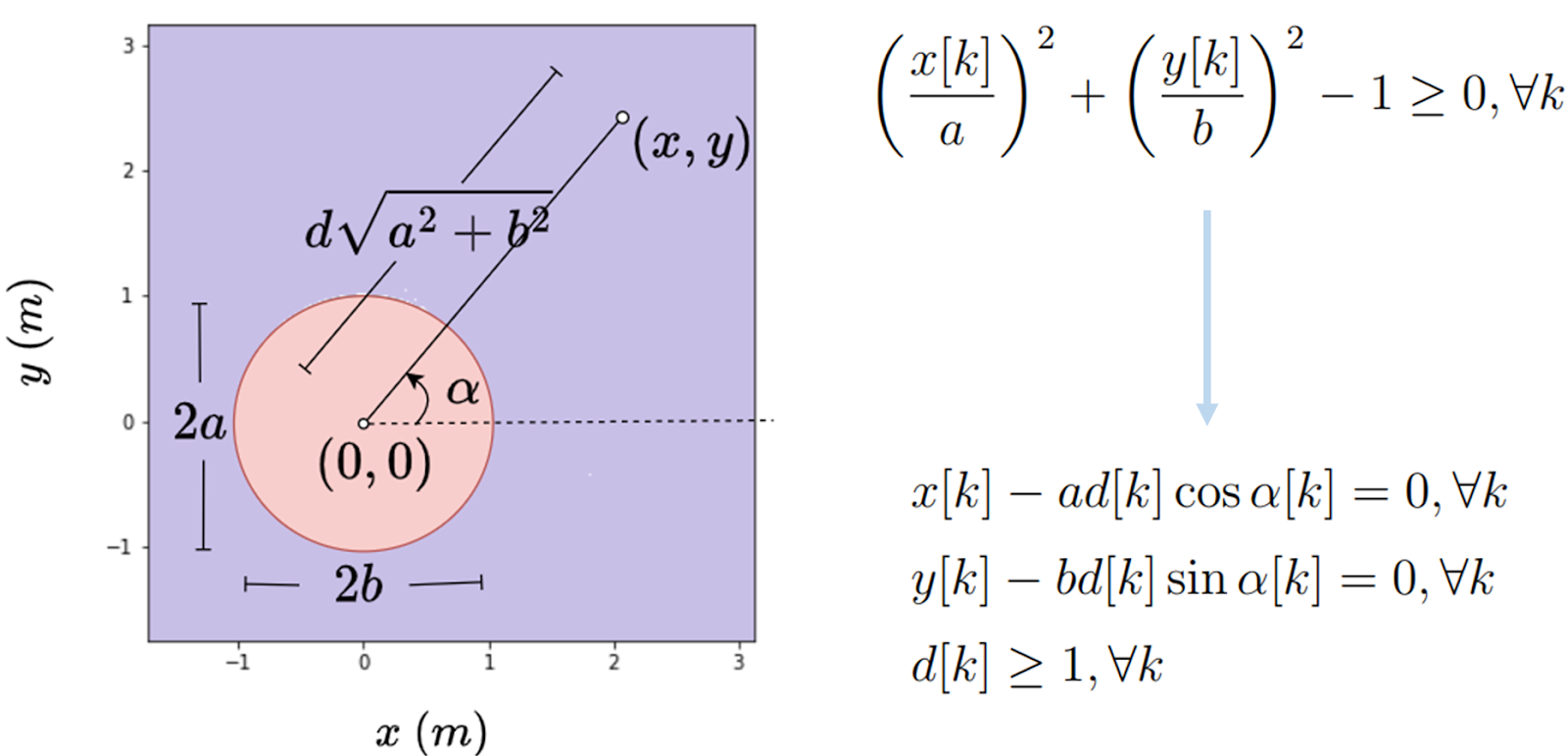
In contrast, our proposed approach obtains a QP without relying on the previously mentioned approximations. The first ingredient is the polar reformulation of collision avoidance and kinematic constraints. An example of the 2D polar reformulation of collision avoidance constraints is shown below:
Fig. Example illustration of polar reformulation of 2D collision avoidance constraints.
The second ingredient is to relax the reformulated constraints as l-2 penalties into the cost function and apply Alternating Minimization. Alternating Minimization results in subproblems that are convex QPs, and some have closed-form solutions, thus obtaining a QP form without relying on linearization; further details can be found in our paper [3]. We can also use and reformulate alternative collision avoidance constraints, barrier function (BF) constraints
where hij is the Euclidean distance between quadrotor i and quadrotor j, and the parameter γ controls how fast the quadrotor i is allowed to approach the boundary of quadrotor j.
Results
We experimentally demonstrate our approach on a 12 Crazyflie 2.0 swarm testbed in challenging scenes: obstacle-free, obstacle-rich, shared workspace with a human. The experimental video is provided below:
In the simulation, we compare our approach against two SCP approaches: SCP (Continuous) [2] enforces constraints across the entire horizon, while SCP (On-demand) [1] enforces only on the first predicted collision. Our (Axiswise) includes box kinematic constraints, while Our (Quadratic) preserves the original quadratic constraints.
From our simulation results, we see that SCP (On-demand) has a lower compute time than SCP (Continuous), as SCP (On-demand) enforces fewer constraints. But, this compute time trend comes at the expense of success rate. On the contrary, our approaches achieve a high success rate with low compute times. Ours (Quadratic) has a slightly higher success rate than Ours (Axiswise) as it has access to large kinematic bounds.
Fig. Simulation results from 100 start-goal configurations with swarm sizes ranging from 10 to 50 in a cluttered environment with 16 cylindrical static obstacles.
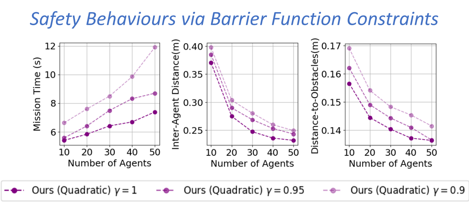
Fig. Simulation results from 100 start-goal configurations with swarm sizes ranging from 10 to 50 and three different γvalues in a cluttered environment with 16 cylindrical static obstacles.
On average, our approaches achieved a 72% success rate improvement, a 36% reduction in mission time, and 42x faster per-agent computation time—our approach trades-off mission time with inter-agent clearance and distance to obstacles via BF constraints.
Outlook
In this work, we presented an online and scalable trajectory planning algorithm for quadrotor swarms in cluttered environments that do not rely on the linearization of collision avoidance constraints and axis-wise decoupling of kinematic constraints. We do so by reformulating the quadratic constraints to a polar form and applying alternating minimization to the resulting problem. Consequently, our planner achieves high scalability and low computation times than existing approaches. We also show that we can reformulate barrier function constraints to introduce safety behaviours in the swarm. One of the future works is to extend the approach to navigate the swarm in a complex 3D environment.
References
[1] Luis, Carlos E., Marijan Vukosavljev, and Angela P. Schoellig. “Online trajectory generation with distributed model predictive control for multi-robot motion planning.” IEEE Robotics and Automation Letters 5.2 (2020): 604-611.
[2] E. Soria, F. Schiano and D. Floreano, “Distributed Predictive Drone Swarms in Cluttered Environments,” in IEEE Robotics and Automation Letters, vol. 7, no. 1, pp. 73-80, Jan. 2022, doi: 10.1109/LRA.2021.3118091.
[3] V. K. Adajania, S. Zhou, A. K. Singh and A. P. Schoellig, “AMSwarm: An Alternating Minimization Approach for Safe Motion Planning of Quadrotor Swarms in Cluttered Environments,” 2023 IEEE International Conference on Robotics and Automation (ICRA), London, United Kingdom, 2023, pp. 1421-1427, doi: 10.1109/ICRA48891.2023.10161063.
The authors are with the Learning Systems and Robotics Lab at the University of Toronto and the Technical University of Munich. The authors are also affiliated with the Vector Institute for Artificial Intelligence and the University of Toronto Robotics Institute (RI) in Canada and the Munich Institute of Robotics and Machine Intelligence (MIRMI) in Germany.
Feel free to contact us with any questions or ideas: vivek.adajania@robotics.utias.utoronto.ca. Please cite this as:
@INPROCEEDINGS{
adajania2023amswarm,
author={Adajania, Vivek K. and Zhou, Siqi and Singh, Arun Kumar and Schoellig, Angela P.},
booktitle={2023 IEEE International Conference on Robotics and Automation (ICRA)},
title={AMSwarm: An Alternating Minimization Approach for Safe Motion Planning of Quadrotor Swarms in Cluttered Environments},
year={2023},
pages={1421-1427},
doi={10.1109/ICRA48891.2023.10161063}
}