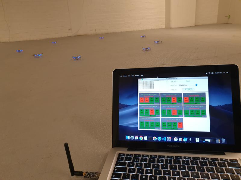
We have briefly mentioned the Active marker deck earlier in our blog and in this post we will describe how it works and what it is all about.
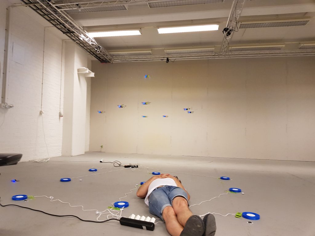
The Active marker deck is a result of our collaboration with Qualisys, a Swedish manufacturer of high end optical tracking systems. Optical tracking systems are often referred to as motion capture (mocap) systems and are using cameras to track markers on an object. By using multiple cameras it is possible to calculate the 3D position of the markers and the object they are attached to with very high precision and accuracy. It is common to use mocap systems in robotic labs to track the position and orientation of robots, for instance quadrotors.
Passive markers
The most common marker type is the passive marker, that is reflective spheres that are attached to the robot. By using infrared flashes on the cameras, the visibility of the markers is maximized and it makes it easier for the system to detect and track them. We are selling the Motion capture marker deck to make it easy to attach markers to a Crazyflie.
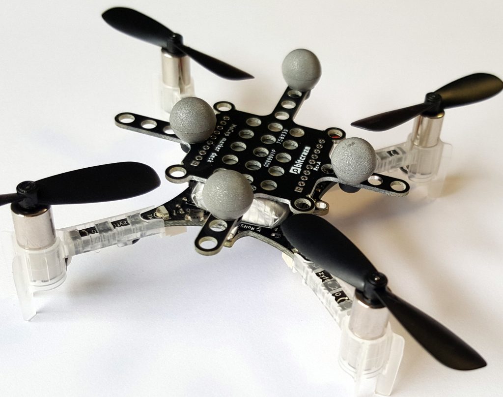
To get the full pose (position, roll, pitch, yaw) of a robot, the markers must be placed in a configuration that makes it possible for the mocap system to identify the orientation. This means that there must be some asymmetry in the marker positions to understand what is front, back, up, down and so on.
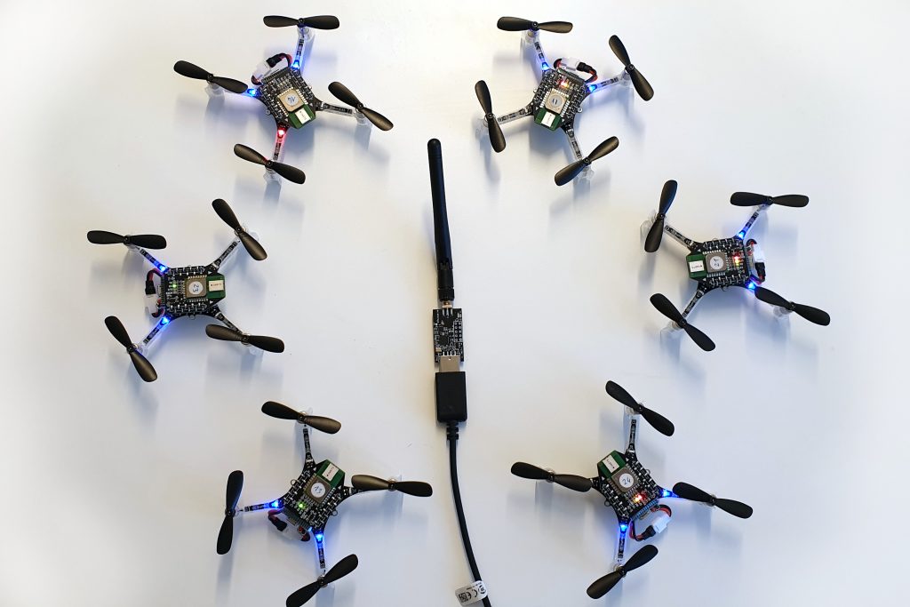
With a swarm of Crazyflies, unique marker configurations makes it possible to distinguish one individual from another and track all drones simultaneously. With a larger number of robots it becomes cumbersome though to place markers in unique configurations, and one approach to solving this problem is to have known start positions for all individuals and keep track of their motions over time instead. This solution is used in the Crazyswarm for instance and all Crazyflies can use the same marker configuration in this setup. Another approach is to make it possible to distinguish one marker from another, enter the Active marker deck.
Active markers
It is possible to use infrared LEDs instead of the passive markers, this is called active markers. The LEDs are triggered by the flash from the cameras and they are easily detected as strong points of light. Since they are emitting light they can be detected further away from the camera than a passive marker and the smaller physical size also keeps them more separated when they are far away and only a few pixels are available to detect them in the camera.
Furthermore Qualisys has a technology that makes it possible to assign an id to each marker and that enables the tracking system to identify individual markers and thus uniquely identify individuals in a swarm. With different IDs on the markers, there is no need have asymmetrical configurations and the marker layout can be the same on all drones. It also reduces the risk of errors in the estimated pose, since there is more information available.
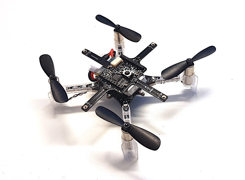
The deck
The Active marker deck is designed to go on top of the Crazyflie and has four arms with one LED each. The arms are as long as possible to maximize the signal/noise ratio in the cameras, while still short enough to be protected from crashes by the motors. There is a STM32 F0 on the deck that takes care of the LEDs and handling of IDs and the main Crazyflie CPU does not have to spend any time on this.
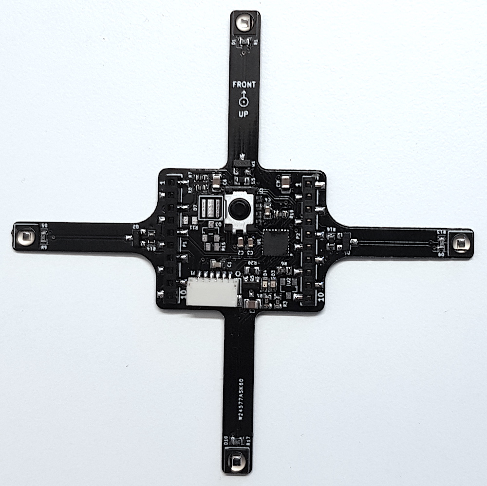
The status of the deck is that the hardware is fully functional (we might want to move something around before we produce it though) and that there is a basic implementation of the firmware. IDs are assigned to the markers using parameters in the standard parameter framework in the client or from a script.
We will start production of the deck in the near future and it will be available in the store this autumn. Qualisys added support for rigid bodies using active markers in V2019.3 of the QTM tracking software.