At Bitcraze, we’ve always believed in giving people the tools to explore the world of robotics, and especially flying robotics. We’re still surprised by just how many directions you’ve taken the Crazyflie platform, and the research and innovation areas seem endless. Swarming, autonomy, edge AI, vision, navigation, mapping, coordination, etc. are all examples of areas you are interested in and what you are using the Crazyflie to unlock.
But what about the more human aspects of robots, and the relationships we build with these machines? What does it feel like to share space with a flying system, and how can we see drones not only as tools, but companions? And how can we help push social robots from academic theory into everyday life?
These are the kinds of questions we’ve been exploring at Bitcraze and with the Drone Gymnasium, we finally have a space designed to push those ideas further.
A Living Lab for Shared Spaces
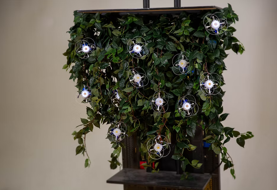
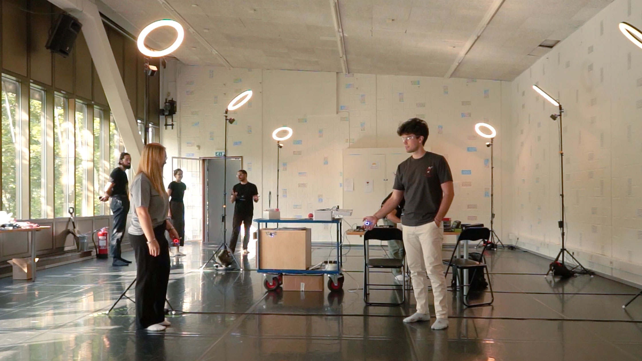
Partially inspired by science fiction, The Drone Gymnasium is an experimental playground brought to life by our industrial postdoc Dr. Joseph La Delfa, toghether with Rachael Garrett, Kristina Höök and Luca Mottola, in collaboration with KTH (Royal Institute of Technology), Digital Futures. and RISE.
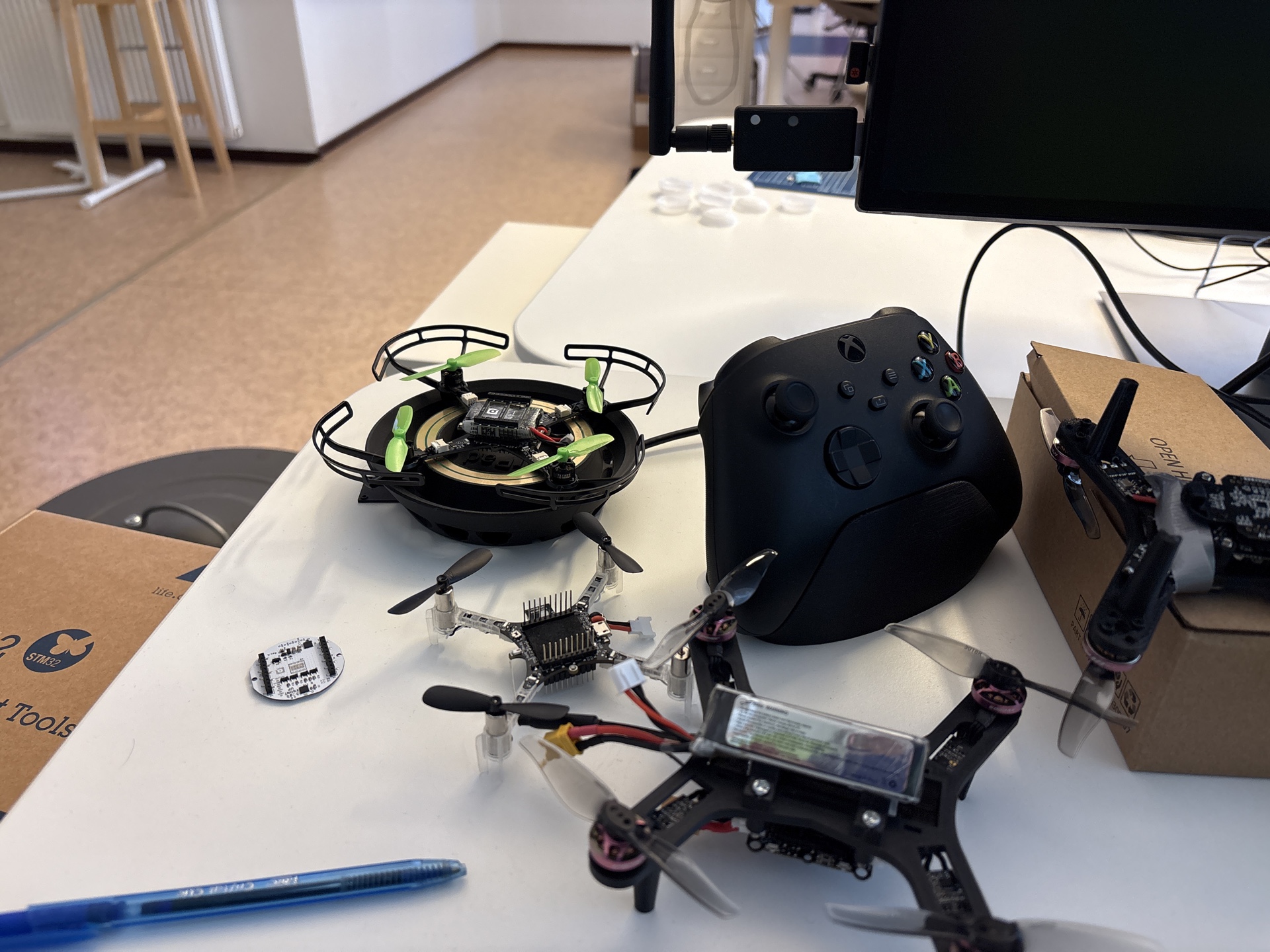
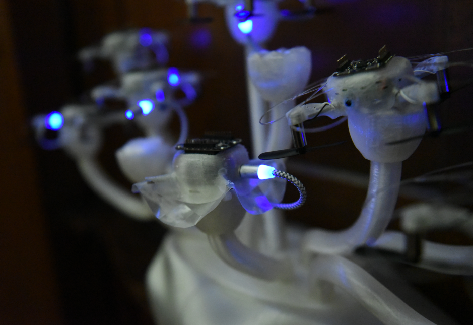
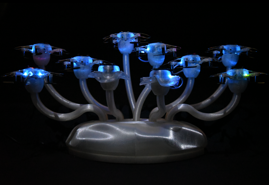
It’s a living lab, where the boundaries between code, design, behavior, and imagination are blurred. A temporary, yet functional, “future lab” where people experiment with how flying robots might one day fit seamlessly into real-world environments. How they could share space with people, not just in theory, but in practice.
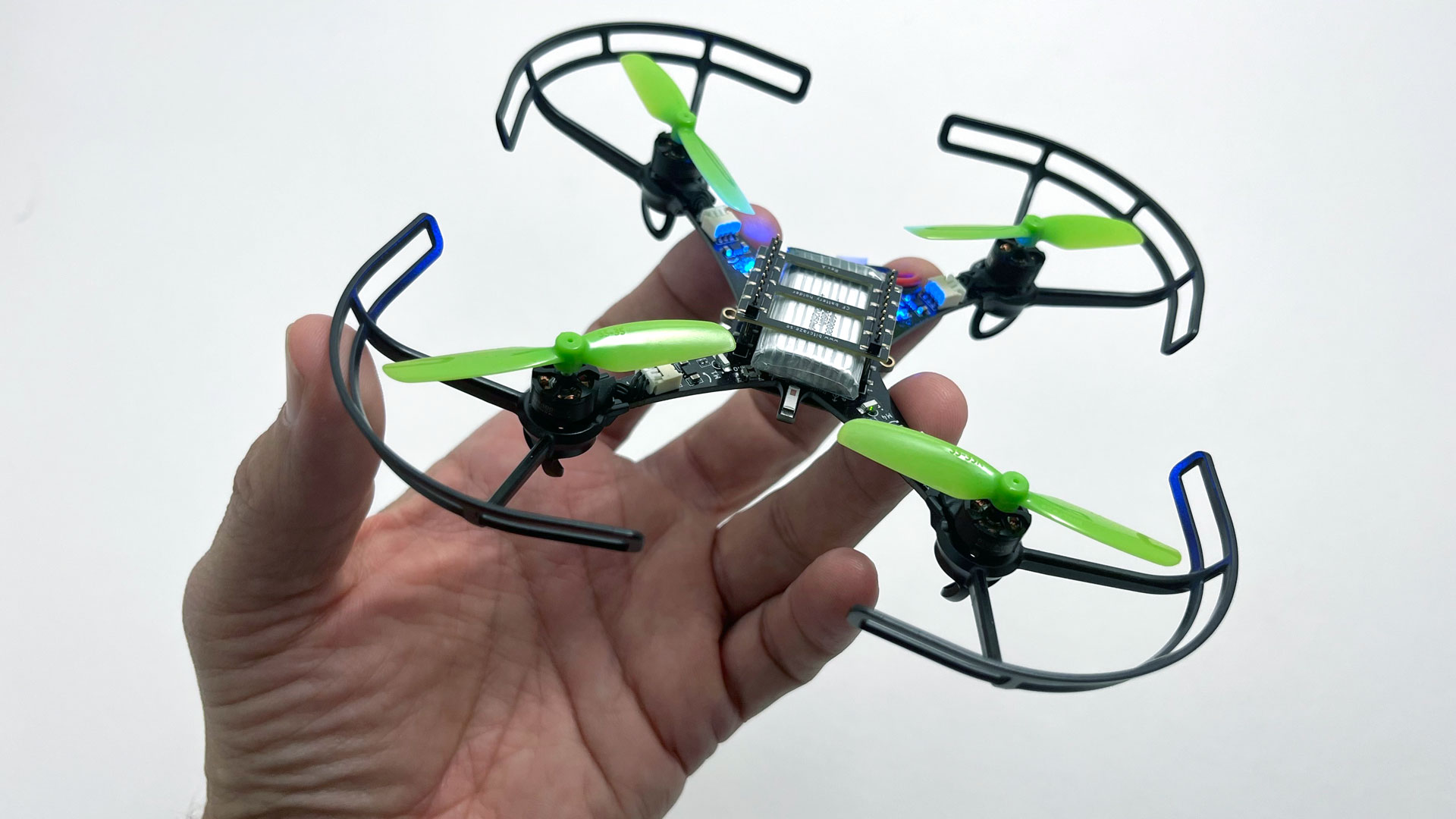
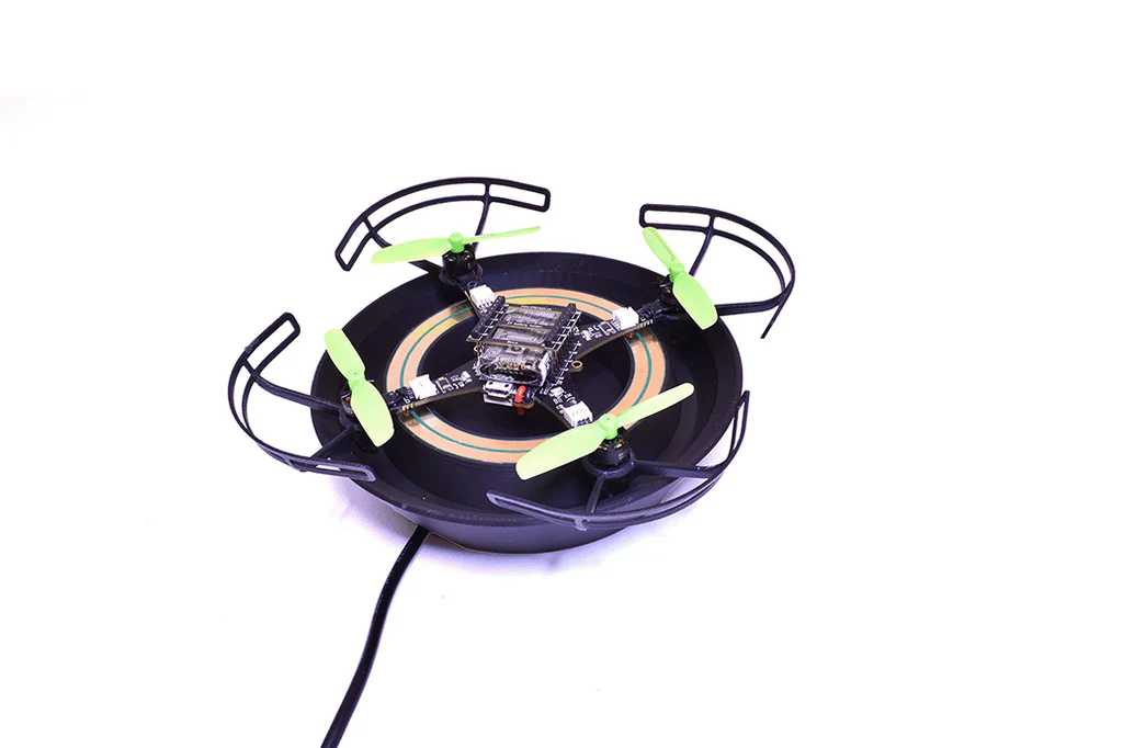
Students from the Physical Interaction Design course, together with our own drone experts, prototyped new robotic experiences using the Crazyflie platform, not just as flying hardware, but as social agents in motion.
From Lab to Real Life
One of the great unsolved challenges of social robotics is translation, moving from controlled lab setups into the beautiful, messy, complexity of the real world.
That’s where many good ideas stumble. That’s also where the Crazyflie shines.
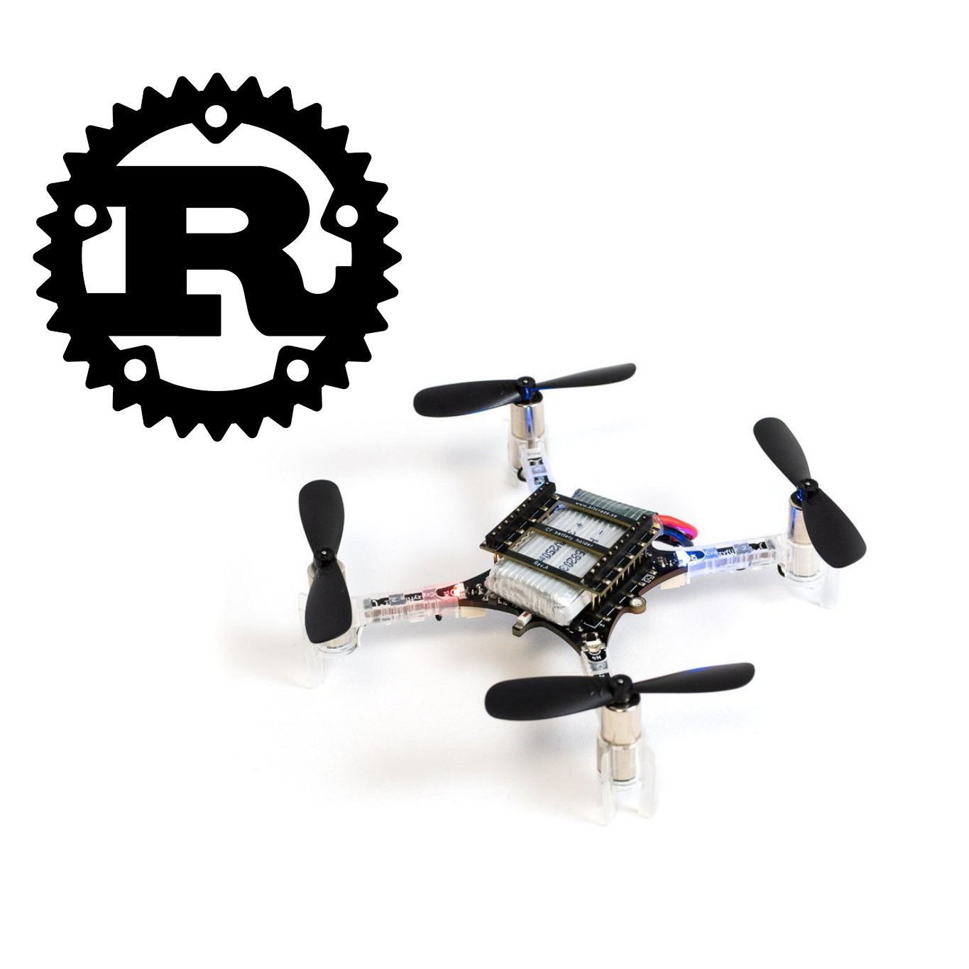
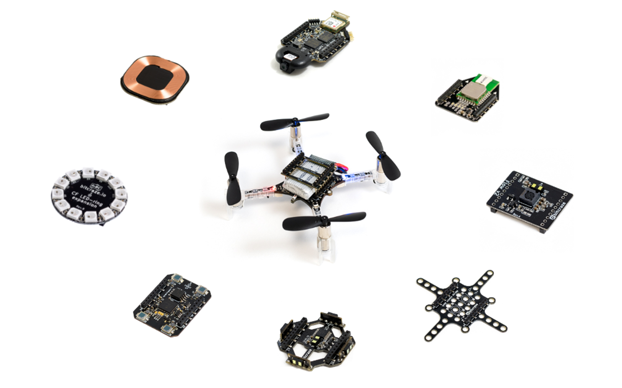
Open, modular, and programmable down to the bone, the Crazyflie gives researchers and innovators permission to try things. To test, break, rebuild, and then observe how it feels to share a room with a machine that moves and reacts in the same space as you.
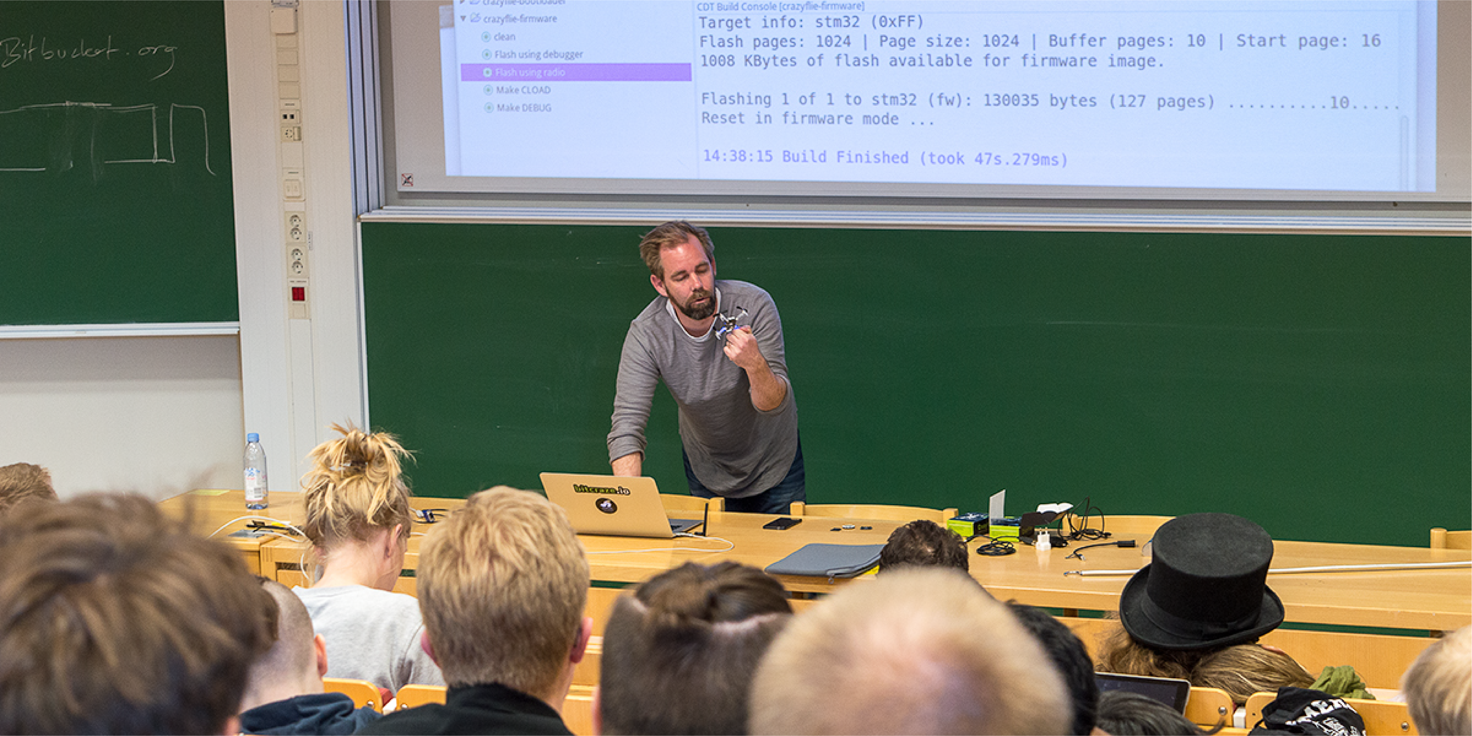
The Drone Gymnasium is one of many ways we’re trying to support academia, not just in supplying hardware, but in co-creating learning environments where ideas around autonomy, behavior, and social interaction can be explored hands-on, in full view of the community.
Asking Better Questions
And the results are exciting. From emergent swarm behaviors to subtle gestures and sound cues, the participants in the Drone Gymnasium weren’t just building tech, they were testing social contracts. What makes a drone feel present instead of intrusive? Helpful instead of unsettling?
That’s not only an academic question. It’s a design question. And a human robotics question.
We believe spaces like this are interesting, not only to prepare the next generation of roboticists, but to ask better questions about what we’re actually building, and for whom.