The AI-deck is now available in our online store! Super-edge-computing is now possible on your Crazyflie thanks to the GAP8 IoT application processor from GreenWaves Technologies. GAP8 delivers over 10 GOPS of compute power at exceptionally low power consumption enabling complex tasks such as path-finding and target following on the Crazyflie, consuming less than 0,1% of the total energy.
The AI-deck can host artificial intelligence-based workloads like Convolutional Neural Networks onboard. This will open up many research areas focusing on fully onboard autonomous navigation of tiny MAVs, like ETH Zurich’s PULP-Dronet. Moreover, there is also ESP32 WiFi connectivity with the possibility to stream the images to your personal computer.
We are happy that we managed to get everything ready so soon after our last update. Crazyflie AI-deck is in early access, which means the hardware design is now finalized and full support for building, running and debugging applications (including GreenWaves’ GAPflow tools for porting neural networks to GAP from TensorFlow) is available, however, limited examples of specific AI-deck applications have been developed so far. Read more about early access here. Even though there is still some work to be done, there are already some examples you can try out which we will explain in this blog post. Also, we aim to have all AI-decks pre-flashed with the WiFi streamer example so that you check out right away if your AI-deck is working.
Beware that you need an JTAG-enabled programmer/debugger in order to develop for the AI-deck!
Technical specifications
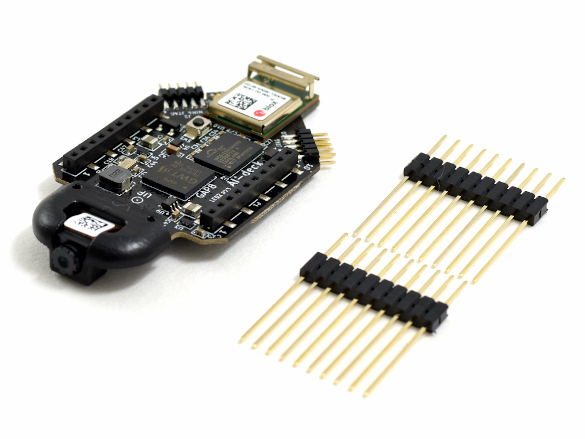
The AI-deck will come with two elongated male pin-headers, which enables the user to connect it to the Crazyflie with an additional deck. There are two 10 pin JTAG connectors soldered which enables connection with a JTAG-enabled programmer. This will be the main way to program the GAP8 chip and the ESP-based NINA module while it is still in early access.
Getting started
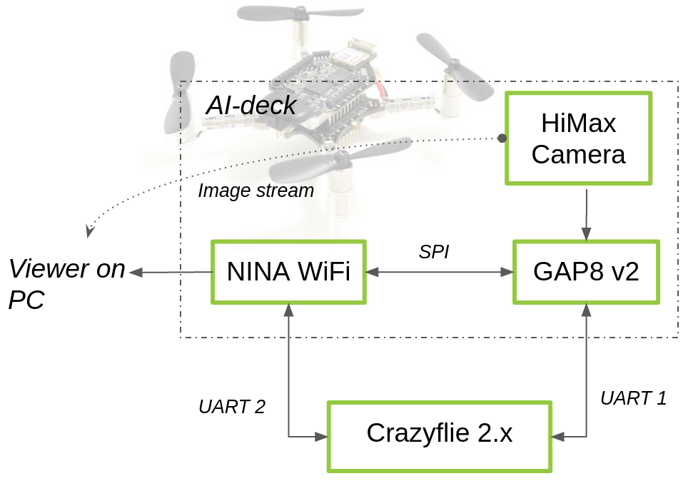
When you first receive your AI-deck, it should be flashed with a WiFi streamer example of the camera image stream. Once the AI-deck is powered up by the Crazyflie, it will automatically create a hotspot called ‘Bitcraze AI-deck Example’. In this repo in the folder named ‘NINA’ you will find a file called viewer.py. If you run this with python (preferably version 3), you will be able to see the camera image stream on your computer. This will confirm that your AI-deck is working.
Next step is to go to the docs folder of the AI-deck examples repository. Try out the WiFi demo and set up your development program with the getting-started guide. This guide contains links to the GAP-SDK documentation from GreenWaves Technologies. You can read more about the face detector example that we demonstrated in this blog post.
It has been a while since we have updated you all on the AI deck. The last full blogpost was in October, with some small updates here and there. It is not that we have not focused on it at all; on the contrary… this has been a high priority project for a while now. It is just quite a complex board with a lot of bells and whistles, which can be challenging to work with sometimes so early in development, something that our previous intern can definitely agree on. So therefore we rather wanted to wait until we were able to make sufficient progress before we gave you an update… and so we have!
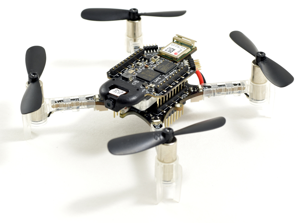
A Crazyflie 2.1 with the AI deck
Together with Greenwaves technologies we have been trying to get the SDK of the GAP8 chip on the AI deck stable enough for an early release. The latest release of the SDK (version 3.4) has proved itself to work with relative ease on the AI deck after extensive testing. Currently it is possible to use OpenOCD for flashing and debugging, and it supports most commonly available debuggers with a jtag connector. In the upcoming weeks both of Bitcraze and Greenwaves will test and try out all examples of the SDK on the AI deck to make sure that everything is still compatible. Also the documentation will be extended as well. As there is so much to document, it might be difficult to catch all of it. However, if you notify us and Greenwaves on anything that is missing once the AIdeck is out, that will help us out to catch the knowledge gaps.
The AI deck also contains the ESP-basedNINA module for establishing a WiFi connection. This enables the users to stream the video stream of the AI deck onto their computers, which will be quite an essential tool if they would like to generate their own image database for training the CNNs for the GAP8 (and it happens to also be quite practical for debugging by the way!). Currently it is required to set credentials of your local WiFi network and reflash the AI-deck to be able to connect and streaming the images, but we are working on turning the Nina into an access-point instead so no reflashing would be required. We hope that we will be able to implement this before the release.
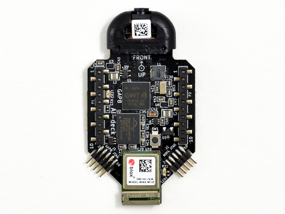
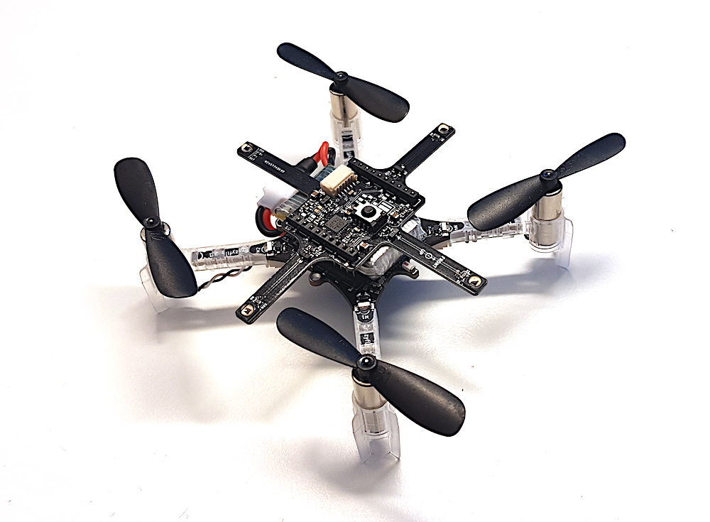
Top view of the AI deck
We are also trying out to adjust applications to make suitable of the AI deck. For instance, we have adapted Greenwaves’ face-detector example to use the image streamer instead of the display available on the GAPuino boards. You can see a video of the result here underneath. Beware that this face-detector is not based on a CNN but on HOG descriptors, so it only works in good conditions where the face is well lit. However, it is possible to train a CNN to detect faces in Tensorflow and flash this on the AI deck with the GAPflow framework as developed by Greenwaves. At Bitcraze we haven’t managed to try that out ourselves ( we are close to that though!) but at least this example is a nice demonstration of the AI deck’s abilities together with the WiFi-streamer. This example and more testing code can be found in our experimental repo here. For examples of GAPflow, please check out the examples/NNtool section of the GAP8 SDK.
For some reason WordPress has difficulty embedding the video that was supposed to be here, so please check https://youtu.be/0sHh2V6Cq-Q
Seeing how the development has been progressing, we will be comfortable to say that the AI deck could be ready for early release somewhere in the next month, so please keep an eye out on our website! We will continue to test the GAP SDK’s stability and we are very thankful for Greenwaves Technologies with their help so far. We will also work on getting-started guides in order to get acquainted with the AI deck, supplementing the already existing documentation about the GAP8 chip.
Even-though the AI deck will soon be ready for early release, this piece of hardware is not for the faint-hearted and embedded programming experience is a must. But keep in mind that the possibilities with the AI deck are huge, as it will be mean that super-edge-computing on a 30 gram flying platform will be available for anyone. It will all be worth it when you have your Crazyflie flying autonomously while being able to recognize its surroundings :)
We have a guest blog post this week from Christopher Banks at Georgia Tech, where he tells us about their work with the Robotarium. Enjoy!
Multi-Agent Aerial Robotics
In the GRITS Lab we focus on autonomous control and coordination of multi-robot systems with applications in – but not limited to – optimal control, constraint-based control, and hardware development. We are home to the Robotarium [1], a remotely accessible swarm robotics testbed that is free for anyone around the world to use for academic and educational purposes. We have integrated Crazyflies into the Robotarium as the main vehicle for aerial robot swarms due to their small size, quiet operation, and high maneuverability . Also, due to their low inertia, they pose minimal harm to their surroundings if system failures occur. Their small size and robust nature are well suited for flying in an indoor testbed like the Robotarium. As we work towards extending the operation of the Crazyflies in the Robotarium to external users, we encountered some important research questions: How do we guarantee the quadcopters remain “safe” (undamaged) while minimizing modifications to user inputs? How do we develop an easy to use interface for external users, with experience ranging from novice to expert? What commands can be used by external users to control a swarm of robots? This post will briefly describe the ongoing research aimed at solving these questions.
Safety Guarantees
To ensure hardware safety while flying experimental algorithms we have developed Control Barrier Functions (CBFs) for quadcopters, allowing users to give nominal control inputs while obeying some safety constraints for the system (e.g. collision-free trajectory following). In the video below, we give four Crazyflies the commands to fly in a circle. A fifth Crazyflie is then told to fly to waypoints that will intersect the circle and attempt to collide with the circling quadcopters. Using CBFs a central controller can modify the inputs given to Crazyflies near collision to ensure safe velocity commands that are close as possible to the user intended control [2] . These CBFs can also be designed to ensure safety by bounding the quadcopters to a designated region of the testbed, giving additional safety constraints by protecting areas outside of the motion capture system during flights.
Quadcopters execute pre-planned flight trajectories designed to collide and use CBFs to avoid collisions.
User Interfaces
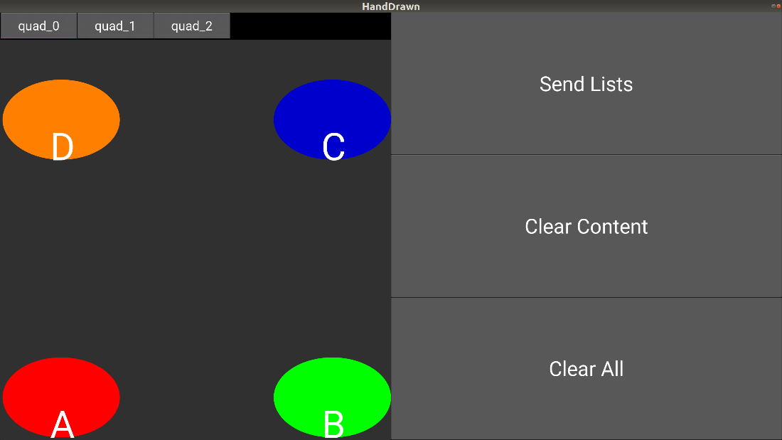
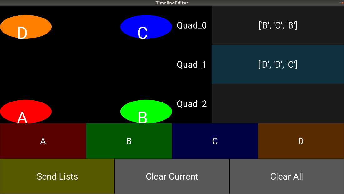
We have also used the Crazyflies to understand how remote users can best interact with the Robotarium both at the interface level and in planning. One project involved studying the effectiveness of graphical user interfaces (GUIs) on swarm robotic control. Two GUIs were developed with different interaction modalities. The GUIs were designed to map user inputs to a set of hoops placed in the Robotarium. One GUI (shown in Fig. 1) provided users the ability to draw paths through a touchscreen interface on a two-dimensional map and then map those inputs to trajectories for a team of robots. The other GUI (illustrated in Fig. 2) allowed users to input a sequence of desired hoops for a team of robots and execute trajectories based on the input.
Figure 1: A GUI that maps hand-drawn paths to inputs for a group of Crazyflies
Figure 2: A GUI that maps the string of indexed hoops as inputs for a group of Crazyflies.
Multi-Agent Planning
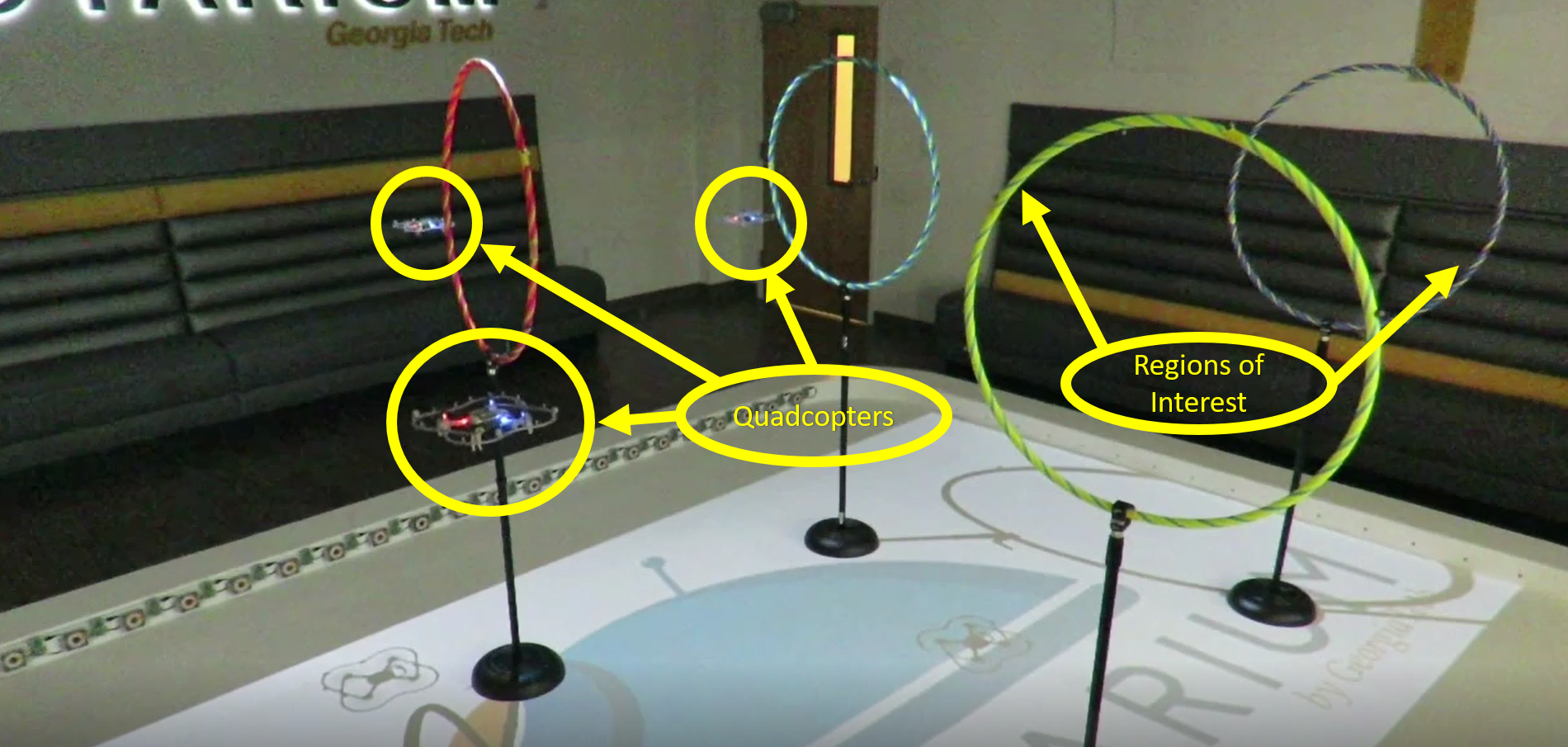
In planning, we looked at how multi-agent planning can be approached using high-level specifications. These high-level specifications allow users to develop plans requiring groups of robots to visit regions of interest (see Fig. 3) and trajectories are generated automatically. To represent these specifications, we use a logic formalism known as temporal logic to encode a preferred sequence of plan execution. As an additional step, users could include constraints on the trajectory by minimizing a cost using stochastic sampling. For more details, see the attached video demonstrating task allocation in a fire-fighting scenario.
Figure 3: Using the multi-agent planning framework, users give high-level specifications that plan trajectories for quadcopters to visit regions of interest (hoops) in the Robotarium.
A optimizing task allocation framework that assigns quadcopters a set of tasks based on user specifications.
Future Directions
As we continue to expand the capabilities of the Robotarium we are looking into how to develop long term autonomy for the Crazyflies. This includes autonomous charging as well as remote access for the lab and other users. We hope to use the Lighthouse system as a method for long term tracking since the Crazyflie will know its position instead of relying on passive tracking from a Vicon system. Our plans also include a lab-based simulator for in house projects related to the Crazyflies as well as updating our system to incorporate Crazyswarm to make control of the Crazyflies easier in implementation. In addition to this, in order to accommodate unknown users, we will have to figure out a control scheme that encourages use from a wide variety of users ranging from novices in quadcopter control to experts. We’ll keep Bitcraze updated on the Robotarium’s progression towards fully autonomous aerial swarms!
Here is another blog post where we try to explain parts of the stabilizer framework of the Crazyflie. Last time, we talked about the controllers and state estimators as part of the stabilizer.c module which was introduced in this blog post back in 2016. Today we will go into the commander framework, which handles the setpoint of the desired states, which the controllers will try to steer the estimated state to.
The Commander module
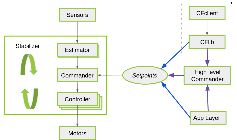
The commander module handles the incoming setpoints from several sources (src/modules/src/commander.c in the firmware). A setpoint can be set directly, either through a python script using the cflib/ cfclient or the app layer (blue pathways in the figure), or by the high-level commander module (purple pathway). The High-level commander in turn, can be controlled remotely from the python library or from inside the Crazyflie.
General framework of the stabilization structure of the crazyflie with setpoint handling. * This part is takes place on the computer through the CFlib for python, so there is also communication protocol in between. It is left out of this schematics for easier understanding.
It is important to realize that the commander module also checks how long ago a setpoint has been received. If it has been a little while (defined by threshold COMMANDER_WDT_TIMEOUT_STABILIZE in commander.c), it will set the attitude angles to 0 on order to keep the Crazyflie stabilized. If this takes longer than COMMANDER_WDT_TIMEOUT_SHUTDOWN, a null setpoint will be given which will result in the Crazyflie shutting down its motors and fall from the sky. This won’t happen if you are using the high level commander.
Setpoint structure
In order to understand the commander module, you must be able to comprehend the setpoint structure. The specific implementation can be found in src/modules/interface/stabilizer_types.h as setpoint_t in the Crazyflie firmware.
There are 2 levels to control, which is:
Position (X, Y, Z)
Attitude (pitch, roll, yaw or in quaternions)
These can be controlled in different modes, namely:
Absolute mode (modeAbs)
Velocity mode (modeVelocity)
Disabled (modeDisable)
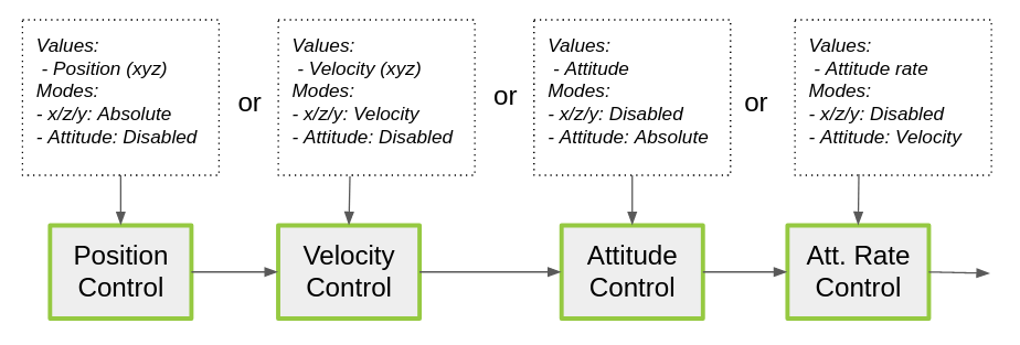
Setpoint structures per controller level
So if absolute position control is desired (go to point (1,0,1) in x,y,z), the controller will obey values given setpoint.position.xyz if setpoint.mode.xyz is set to modeAbs. If you rather want to control velocity (go 0.5 m/s in the x-direction), the controller will listen to the values given in setpoint.velocity.xyz if setpoint.mode.xyz is set to modeVel. All the attitude setpoint modes will be set then to disabled (modeDisabled). If only the attitude should be controlled, then all the position modes are set to modeDisabled. This happens for instance when you are controlling the crazyflie with a controller through the cfclient in attitude mode.
High level commander
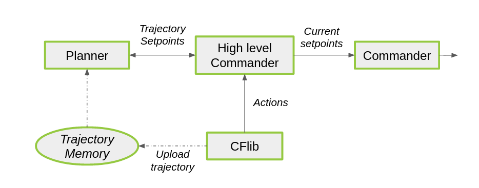
Structure of the high level commander
As already explained before: The high level commander handles the setpoints from within the firmware based on a predefined trajectory. This was merged as part of the Crazyswarm project of the USC ACT lab (see this blogpost). The high-level commander uses a planner to generate smooth trajectories based on actions like ‘take off’, ‘go to’ or ‘land’ with 7th order polynomials. The planner generates a group of setpoints, which will be handled by the High level commander and send one by one to the commander framework.
It is also possible to upload your own custom trajectory to the memory of the Crazyflie, which you can try out with the script examples/autonomous_sequence_high_level of.py the crazyflie python library repository. Please see this blogpost to learn more.
Support in the python lib (CFLib)
There are four main ways to interact with the commander framework from the python library.
Send setpoints directly using the Commander class from the Crazyflie object, this can be seen in the autonomousSequence.py example for instance.
Use the MotionCommander class, as in motion_commander_demo.py. The MotionCommander class exposes a simplified API and sends velocity setpoints continuously based on the methods called.
Use the high level commander directly using the HighLevelCommander class on the Crazyflie object, see autonomous_sequence_high_level.py.
Use the PositionHlCommander class for a simplified API to send commands to the high level commander, see the position_commander_demo.py
Documentation
We are busy documenting the stabilizer framework in the Crazyflie firmware documentation, including the content of this blogpost. If you feel that anything is missing or not explaining clearly enough about the stabilizer framework, please drop a comment below or comment on the forum.
For the users that have subscribed to our github repository this does not come as an surprise, but for the rest, we have released a new version of our Crazyflie firmware (both STM and NRF) last week!
We know that it is quite close to our last release in February, but we had so many changes and contribution that we deemed it necessary to add a stamp to this current version. In this blog-post, we will give an overview on which features to expect in this update.
UART communication
With courtesy of Saarland University, it is now possible to connect the Crazyflie through its UART to a port on your raspberry pi or through an FTDI cable directly to your computer. This is an extra port for communicating with CRTP will open up new possibilities to interact with your crazyflie.
This is compatible with CFlib version 0.1.10, however there was a fix implemented in the current master (see the ticket here). Please see the ticket for the UART communication here if you are interested in the implementation details.
Lighthouse
It is now possible to get the lighthouse geometry (the position and orientation of the base stations) without SteamVR. We made a script based on the latest stable release of openCV, to calculate the base station geometry based on the received sweep angles on the lighthouse deck. Check these full instructions on how to use this new script. It is a very new and fresh implementation, so if you are experiencing any trouble, please leave an issue on this page or leave a comment on the forum.
Also, FPGA v4 is now integrated in 2020.04, which support Basestation v2. This is still in a very early phase and not yet fully integrated in the firmware, so please keep an eye on this ticket for the implementation process in the latest master of the crazyflie-firmware. There was also a blogpost a few weeks ago about the current state of the lighthouse v2 development.
Bluetooth management
We also provided an update of the bluetooth management of the Crazyflie communication by the NRF chip. Before, it was (unintentionally) possible to connect to the Crazyflie over Bluetooth while it also connected to the CFclient through the crazyradio PA. This caused a lot of unwanted elements such as package loss and unresponsiveness. Now, whenever a Crazyradio packet has been received, Bluetooth will automatically be disabled. The same goes for the peer-2-peer packet, so the NRF firmware no longer needs to be flashed without Bluetooth support. The Crazyflie needs to be restarted after connecting through the CF dongle or P2P in order to connect to it again with the Crazyflie mobile app.
General fixes and improvements
Here are the general fixes and improvements listed that has been fixed in release v2020.04:
BMI088 (IMU of the CF2.1) has an self-test now.
Fixed memory issue with the Micro SD card deck.
High-level commander improvements.
Documentation improvements.
LPS TDoA (2 and 3) improvements.
See the release notes of the crazyflie-firmware and crazyflie-nrf-firmware to see the full list of improvements and issues that were fixed in 2020.04. The zip files for the firmware for both the roadrunner (tag) and crazyflie (cf2) can be found here.
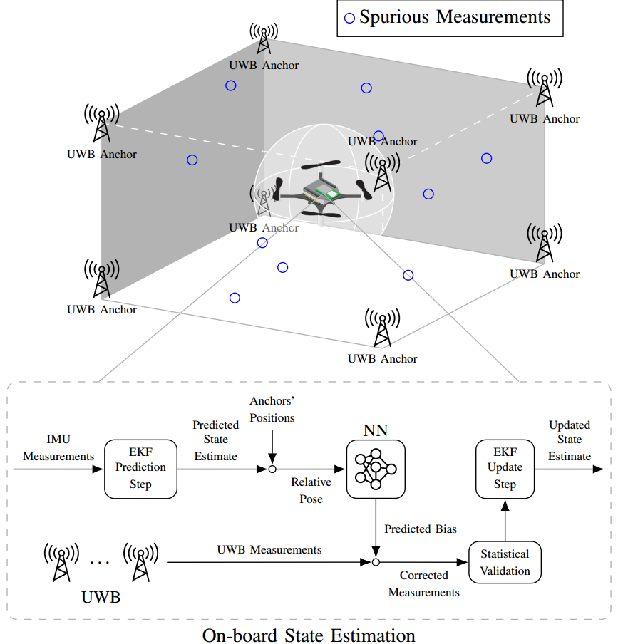
Accurate indoor localization is a crucial enabling technology for many robotic applications, from warehouse management to monitoring tasks. Ultra-wideband (UWB) localization technology, in particular, has been shown to provide robust, high-resolution, and obstacle-penetrating ranging measurements. Nonetheless, UWB measurements are still corrupted by non-line-of-sight (NLOS) communication and spatially-varying biases due to doughnut-shaped antenna radiation pattern. In our recent work, we present a lightweight, two-step measurement correction method to improve the performance of both TWR and TDoA-based UWB localization. We integrate our method into the Extended Kalman Filter (EKF) onboard a Crazyflie and demonstrate a closed-loop position estimation performance with ~20cm root-mean-square (RMS) error.
A stylized depiction of our UWB indoor localization system and the schematics of the proposed estimation framework.
Methodology
UWB measurement errors can be separated into two groups: (1) systematic bias caused by limitations in the UWB antenna pattern and (2) spurious measurements due to NLOS and multi-path propagation. We propose a two-step UWB bias correction approach exploiting machine learning (to address(1)) and statistical testing (to address (2)). The data-driven nature of our approach makes it agnostic to the origin of the measurement errors it corrects.
(1) Neural Network Bias Correction
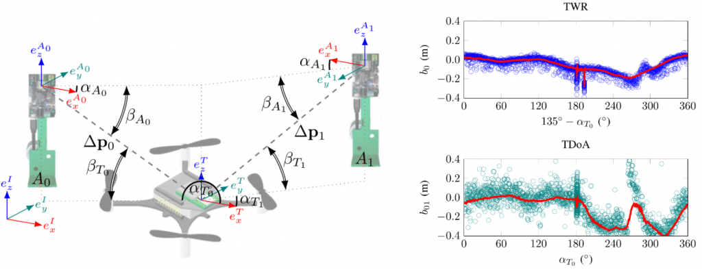
The doughnut-shaped antenna radiation pattern causes the relative poses of anchors and tags to have a noticeable impact on the received signal power, which leads to systematic, predictable biases. To empirically demonstrate the systematic measurement errors resulting from varying the relative pose between anchors and tags, we placed two DWM1000 UWB anchors at a distance of 4m and collected both TWR and TDoA UWB range measurements for the UWB tag mounted on top of a Crazyflie spinning around its own z-axis.
Left: schematics of the ranges (∆p’s), azimuth (α’s) and elevation angles (β’s) defining the relative poses of tag T and anchors A0, A1 when collecting the systematic bias measurements. Right: the neural network’s inferred bias (in red) with respect to the tag’s varying azimuth angle towards anchor T0, αT0, plotted against the UWB raw measurements.
We choose to leverage the nonlinear representation power of neural networks to learn the systematic bias which only depends on anchor-tag relative poses. Considering the limited onboard computation power, we select a fully connected neural network with 50 neurons in each of two layers with ReLU activation. To represent the relative pose between the UWB tag and anchors, we select the relative distance ∆p and roll, pitch, and yaw angles of the quadcopter as the input features x for the network. As we used fixed anchors, we do not include their poses as inputs (this level of generalization is left for future work). Given sufficient training data, the spatially-varying measurement bias can be described by a nonlinear function b=f(x) captured by the trained neural network.
(2) Outlier (Spurious Measurements) Rejection
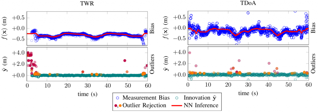
Besides our learning-based bias correction, we use a quadcopter’s dynamic model to filter inconsistent UWB range measurements. Given the estimated velocity v and maximum acceleration amax, we can compute the maximum distance dmax a quadcopter can cover during time ∆t. Based on this information, we can reject unattainable measurements before fusing them into the EKF by comparing the measurement innovation with dmax.
Moreover, we use a statistical hypothesis test to further classify potential outlier measurements. Since the measurement innovation vector is assumed to be distributed according to a multivariate Gaussian distribution, the normalized sum of squares of its values should follow a Chi-square distribution. We use the Chi-square hypothesis test to determine whether a measurement innovation is likely coming from this distribution.
UWB measurement bias f (x) prediction performance of the trained neural network (in red) compared to the actual measurement errors (blue dots) as well as the role of model-based filtering (purple dots) and statistical validation (orange dots) in rejecting outlier measurement innovations (teal dots) during a 60” flight experiment.
Data Collection and Training
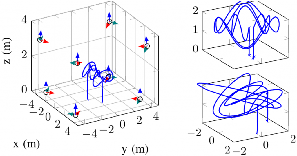
We use a Crazyflie 2.0 quadcopter and the Loco Positioning System (LPS)’s UWB DW1000 modules as our research platforms. Our calibration approach runs on the Crazyflie STM32 microcontroller within the FreeRTOS real-time operating system. We equipped a cuboid flying arena with 8 UWB anchors, one for each vertex. The anchor positions were measured using a Leica total station theodolite.
Left: three-dimensional plot of our flight arena showing the positions and poses of the eight UWB DW1000 anchors (each facing towards its own x-axis, i.e., the red versor). Right: two of the training trajectories we flew to collect the samples that we used to train our neural network-based bias estimator
For all experiments, the ground truth position of the Crazyflie was provided by 10 Vicon cameras. The neural network was trained using PyTorch. To perform inference on the Crazyflie’s microcontroller, we re-use PyTorch’s trained weights in a plain C re-implementation. Since the DW1000 modules in the LPS provide UWB measurements every 5ms, the neural network inference runs at 200Hz during flight as well. Our outlier rejection method is also implemented in plain C and merged with the onboard EKF.
Close-loop Position Estimation Performance
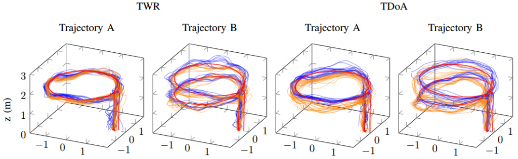
We demonstrate the position estimation and close-loop performance of the proposed methods by flying a Crazyflie quadcopter along planar and non-planar circular trajectories (which were not among the trajectories used for training). A comparison between the estimation error of (A) the UWB localization estimate enhanced with outlier rejections and (B) the estimated enhanced with both outlier rejection and neural network bias compensation is conducted in our experiments for both TWR and TDoA2 modes. We repeated all of our experiments 10 times with a target velocity of 0.375m/s. The quadcopter trajectories during these flight tests are displayed in the following plots.
Flight paths and the tracking performance of our approach with (in blue) and without (in orange) the neural network bias correction for two reference trajectories (planar and non-planar circular orbits) and both UWB modes (TWR and TDoA).
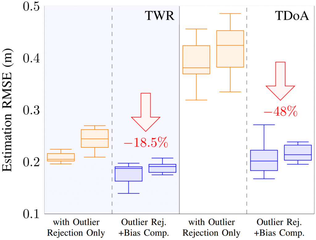
The distributions of the RMS estimation errors are summarized into a box plot. TWR-based ranging results in better localization performance than TDoA. However, we observe that, with our neural network bias compensation, the average RMS error of TDoA localization is around 0.21m, which is comparable to that of TWR-based localization (~0.19m). Thanks to the neural network bias compensation, the average reduction in the RMS error is ~18.5% and 48% for TWR and TDoA, respectively. Most notably, this result suggests that bias compensation might help closing the performance gap between TWR- and TDoA-based localization.
Root mean square error (RMSE) of the quadcopter position estimate before (in orange) and after (in blue) the neural network calibration step for both TWR and TDoA ranging modes. Each pair of box plots refers to a planar reference trajectory (left of each pair) and a reference trajectory with varying z (right of each pair), showing a greater performance enhancement for the latter.
Outlook
In this work, we presented a two-step methodology to improve UWB localization—for both TWR- and TDoA-based measurements. We used a lightweight neural network to model and compensate for pose-dependent and spatially-varying biases and an outlier rejection mechanism to filter spurious measurements. Through several real world flight experiments tracking different trajectories, we showed that we are able to improve localization accuracy for both TWR and TDoA, granting safer indoor flight. In our future work, we will include the anchors’ pose information to allow our method to further generalize to previously unobserved indoor environments, with different anchor configurations.
Feel free to contact us if you have any questions or ideas: wenda.zhao@robotics.utias.utoronto.ca. Please cite this as:
<code>@article{wenda2020learning,
  title={Learning-based Bias Correction for Ultra-wideband Localization of Resource-constrained Mobile Robots},
  author={Wenda Zhao and Abhishek Goudar and Jacopo Panerati and Angela P. Schoellig},
  journal={arXiv preprint arXiv:2003.09371},
  year={2020}
}</code>
The Lighthouse V2 implementation has been simmering away for a long time in the Bitcraze kitchen and in this blog post we will give you an update on the current status and what is remaining for a full release of this tasty dish.
Crazyflie 2.1 and Lighthouse V2 base station
We believe we have solved most of the major technical hurdles (last famous words) on the way to a working implementation that uses Lighthouse V2 base stations for positioning, now it is mostly work to implement the functionality that is remaining. As described in this post we now have a new FPGA binary that has the ability to decode both V1 and V2 base stations, and this was a major step forward. This new binary is used in the Crazyflie firmware master branch, and if the Lighthouse deck is used with the latest Crazyflie firmware, the new FPGA binary will automatically be flashed to the deck.
What has changed?
The new FPGA binary uses a different UART protocol to communicate with the Crazyflie. This protocol has been implemented in the firmware and hopefully there is no functional difference compared to the previous FPGA binary when using Lighthouse V1 base stations.
We have added a first version of Lighthouse V2 base station decoding, but it is still a bit limited. As a start we decided to “emulate” V1 base stations to be able to reuse as much of the existing code as possible. For now we support only 2 base stations and they must use channel 1 and 2 (used to be called modes). The V2 angles are transformed into V1 angles and fed into the old positioning logic and are handled exactly the same way as before. Even though this works, it is not the optimal solution and we hope to be able to refine it later on.
We have also written a python script to estimate base station geometry (positions and orientation) using the Lighthouse deck. This removed the requirement to use software from Steam which should simplify the set up process. Please see the (still limited) documentation. Note that this calibration method only supports the basestation V1… for now!
There is a lot of code that has been modified and the FPGA implementation is completely new, it is not unlikely that there is functionality that is unstable or broken, or configurations that are not supported. If you happen to notice any bugs, please let us know!
What is remaining?
The functional areas that needs to be implemented or cleaned up before we leave the Early Access stage is the following:
Calibration data
The calibration data is embedded in the modulated light from the base stations and describes imperfections from the manufacturing process for each individual. This data is not read yet for V2 and will increase the precision when available.
Support for more than 2 base stations
Lighthouse V2 base stations are designed for systems with more than 2 base stations. The Crazyflie firmware needs to be extended for this functionality to work, including handling of geometry data, logging, memory management and some other bits and pieces.
Native V2 positioning
The angles from the V2 base station should be fed directly into the kalman filter for positioning, instead of first being transformed into V1 angles. This will increase robustness and reduce data loss.
Client support
We want to add a tab in the python client where a Lighthouse system can be monitored, configured and managed. It should, for instance enable the user to configure and visualize base station geometry.
FPGA binaray management
Currently the FPGA binary is included in the Crazyflie firmware and it is automatically uploaded to the deck when booted. This is not a viable long term solution and we hope to be able to find a more generic way of handling deck binaries.
Conclusions
As can be seen, there is still quite some work to be done before the Lighthouse V2 stew is ready to be served, but we are definitely starting to smell some nice flavours from the kitchen!
Finally a view from Kristoffer’s home lab, currently in the summer house. Three base stations are set up as a Fun Friday hack to see what it would take to use more than 2. Luckily it did not take too much time to get this to work :-)
In this blog-post we wanted to give you guys an overview of our running projects and a general update of the status of things! We got settled in our home-labs and are working on many projects in parallel. There are a lot of development happening at the moment, but the general feeling is that we do miss working with each other at our office! With our daily slack Bitcraze sync meetings and virtual fikapause (Swedish for coffee breaks), we try to substitute what we can. In the mean time, we are going on a roll with finishing all our goals we have set at our latest quarterly meeting, so here you can read about those developments.
AI-deck
Crazyflie with AI-deck
The last time we gave an update about the AI-deck was in this blog post and in the final post of our intern Zhouxin. Building on his work, we are now refocusing on getting the AI-deck ready for early release. The last hurdle is mostly software wise on which we are considering several approaches together with the manufacturer of the Gap8 chip Greenwaves technologies. Currently we are preparing small testing functions as examples of the different elements of the AI-deck in our repo, which are all still in a very primarily phase.
Even though we still need some time to finalize the AI-deck’s early release, we will consider sending an early version of the AI-deck if you are willing to provide feedback while working with it. Please fill in the form and we will get back to you.
Lighthouse
We have made quite some progress on the development for the lighthouse V2. Kristoffer has been working hard from his homelab to get a seamless integration of both V1 and V2 in our firmware (check out this github issue for updates). Currently it is still very untested and very much in progress, however we do have a little preview for you to enjoy.
Crazyflie with LH basestation v2
Documentation
Right now, we are also doing a lot of revamping of the large web of documentation. Unfortunately this is a lot of work! As you noticed by now, we have added overview pages to guide the reader to the right information. We also have moved the tutorials to another part of the menu to avoid clutter on our website. In general we try to go through the repository docs to see if there is any information missing or outdated, however please let us know if you have encountered an error in any description or are missing crucial elements.
Our latest task is revamping the product pages as well, by putting all the necessary information about the hardware in just one place. Also, we are planning to make (video) tutorials soon about many elements of the Crazyflie and how to work with it. More about that later!
Production and Shipment
Production at our manufacturers in China are slowly starting up again. Although it is not yet back at full force, it does enable us to already start ordering to replenish our stock and to get started with finishing our test rigs. Moreover, we are also negotiating to resolve the propeller issue we mentioned earlier, but there is no update on that so far.
As mentioned in this blogpost, we are still shipping orders about twice a week. Both DHL and Fedex are functioning as normal, but we do notice that there is a delay of a few extra days on some deliveries. Please keep that in mind when ordering at our webshop.
Many people in the world have now settled in the reality of working from home. We have also taken precautions ourselves by not go to our office as normal and only ship out packages a few times per week instead of every day (see this blogpost). This also means that we do not have full access to our lab with all our equipment and positioning systems in our big 10 x 10 meter flight lab at the office. In this blogpost we will show how we manage to keep on developing and flying, even in the current situation.
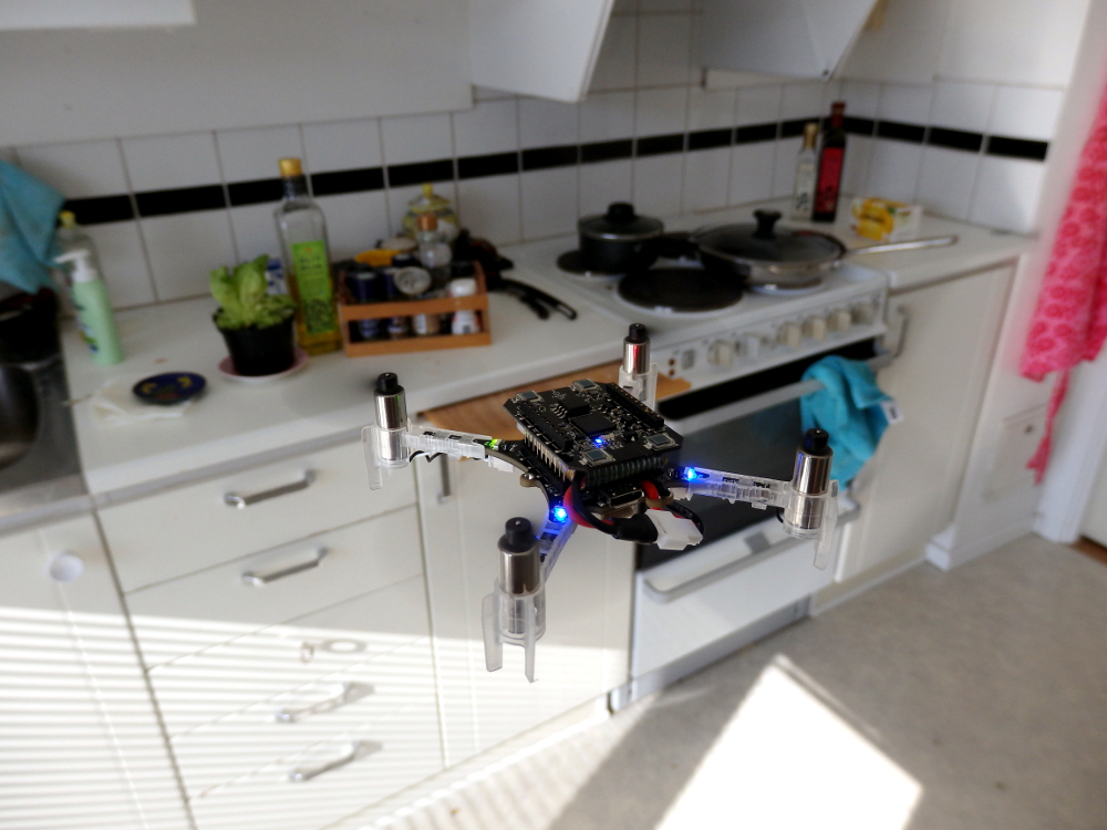
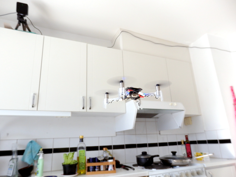
Crazyflie flying in a kitchen with the lighthouse deck
In(light)house positioning
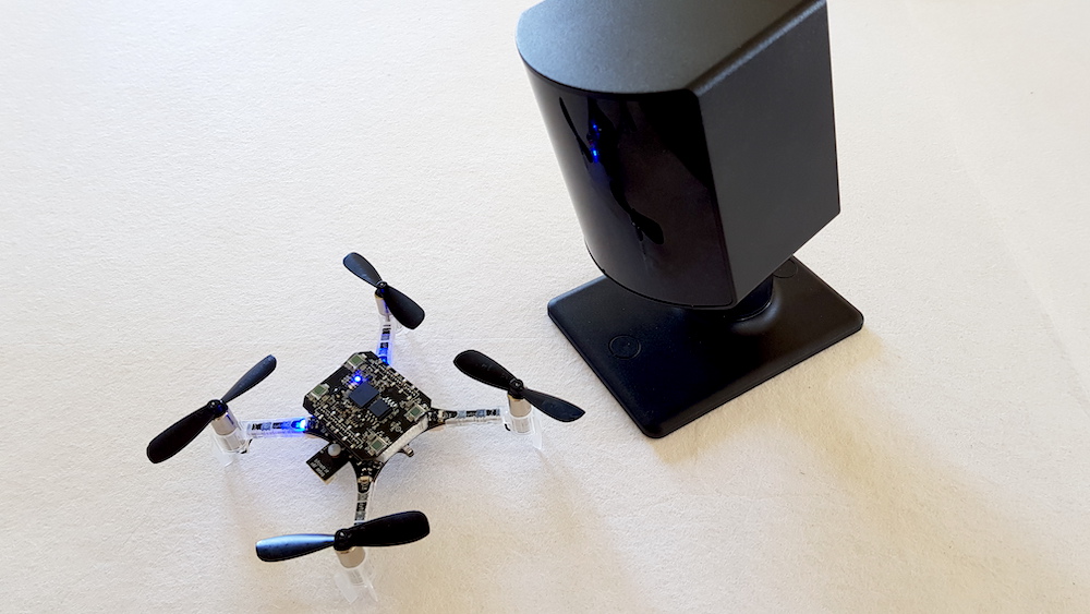
Currently we started to use the Lighthouse positioning system to setup up the remote home lab at our houses. As of recent additions to the Crazyflie firmware, it has been made easy to get the geometry data from the base station. Now the only items we need for indoor flight are just two (or only one) lighthouse basestations V1’s and a Crazyflie, and that is it! There is no need for an HTC Vive headset or hub, or third-party software like SteamVR and the setup is finished in 2 minutes! Check out the new documentation here if you want to know more about the new setup of the lighthouse positioning system.
Also, we recently got a very primarily version of the lighthouse V2 working (see here) and we of course want to keep the momentum going! We will be working on full compatibility from our homes so stay tuned. For now, see this video of the Crazyflie flying with just a single base-station, taken from one of our team-member’s home lab.
Remote Lecture Hall and Practicals
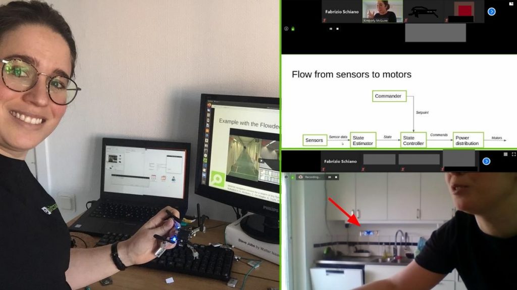
We were invited by Dario Floreano and Fabrizio Schiano from the EPFL-LIS laboratory to do a lecture for the ‘Aerial Robotics’ Course as part of EPFL’s Master’s program in Robotics. Due to the virus, we had to cancel our trip to go there physically… but luckily we were able to do the lecture remotely anyway!
Screenshots of the lectures
The lecture consists of two parts. In the first hour we mostly explained about the Crazyflie ecosystem, hardware and sensors. In the second hour we focused on how the stabilization module worked, including the controllers and the state estimation. During both sessions, we alternated between the theory slides with actual hands-on demos. The lighthouse positioning system was setup in a kitchens, so that we were able to show full flights and practicals with the Crazyflie. At the end there was also the push-demo with just the flowdeck and multiranger, which didn’t use any external positioning at all.
The lectures can be found below and the documentation has been updated as well with the covered material (see here). Be sure to check out the controller tuning presented in part 2 of the lecture (25:00 – Cascaded PID controller).
We know that there are currently users that are moving their flight lab from their university or company to their homes to be able to continue their work. We would love to hear about your experience and your home lab! Send us an email with your story to contact@bitcraze.io, drop us a message on forum.bitcraze.io, or mention us in your Twitter, Linkedin, Facebook or Reddit post. Also, if you want to setup your own home lab and you need any advice or help, please let us know!
We have mentioned the Active Marker deck in an earlier blog post, and are now happy to announce that it has been released and is available in our store.
Crazyflie with Active marker deck
By changing the passive, reflective markers to active, IR-LEDs, it is possible to improve the detection of markers in the cameras. There are two main reasons: the area of the marker is smaller and easier to separate from other markers close by, and the LEDs are emitting light and can be detected further away.
The deck has been developed in collaboration with Qualisys and together with the QTM system, it utilizes their Active Marker technology. An ID is assigned to each marker, and since the identity of each marker can be detected by the MoCap system, it is possible to estimate the full body pose of the Crazyflie without unique marker positions or known starting positions. IDs are easily assigned using the parameter sub system of the Crazyflie.
Even though the deck mainly is intended to be used with Qualisys MoCap systems, the LED markers can also be configured to be on or off which we hope might be useful in other applications as well.