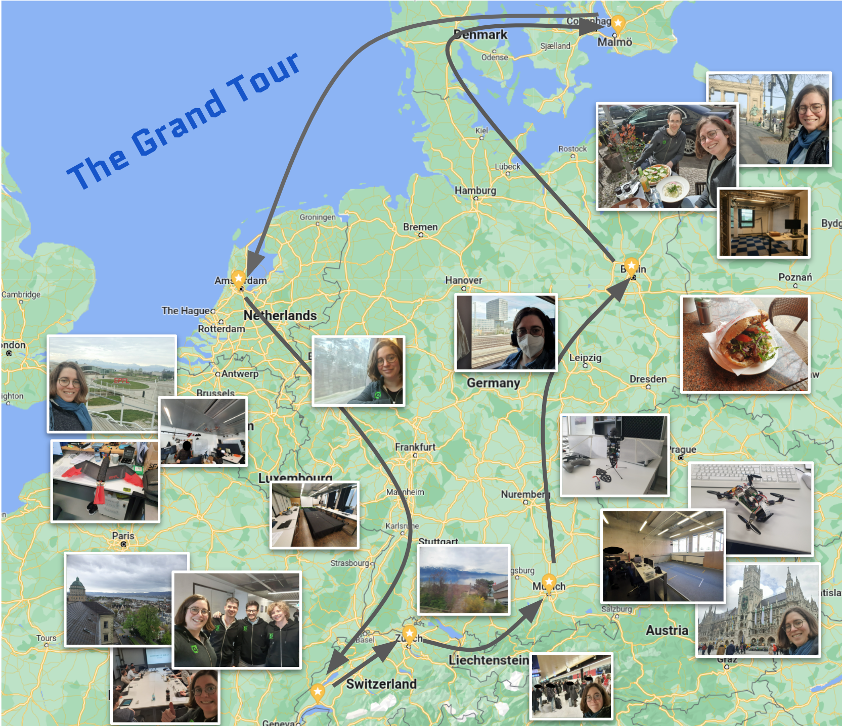
In the first years that I started at Bitcraze I’ve been focused mostly on embedded development and algorithmic design like the app layer, controllers and estimators and such, however recently I started to be quite interested in the robotic integration between the Crazyflie and other (open-source) projects and users. This means that I’ll be dwelling more often in the space between Bitcraze and the community, which is something that I do really enjoy I noticed during the Grand Tour. It also initiated my work with simulators which I think would be very useful for the community too. The summer fun project that I’ve been now working on is to integrate the Crazyflie with ROS2 to integrate standard navigational packages, which will be the topic of this blogpost!
ROS2 Crazyflie Node
So first I worked on the ROS2 node that actually communicates with the Crazyflie directly. I think many of you are familiar with the USC’s CrazySwarm project, of which the ROS2 variant, CrazySwarm2, is already available for most functionalities. Even though the name says CrazySwarm, this can be very easily used for only one Crazyflie too. The CrazySwam2 is currently under more development by the IMRClab of TU Berlin, but please take a look if you want to give it a go!
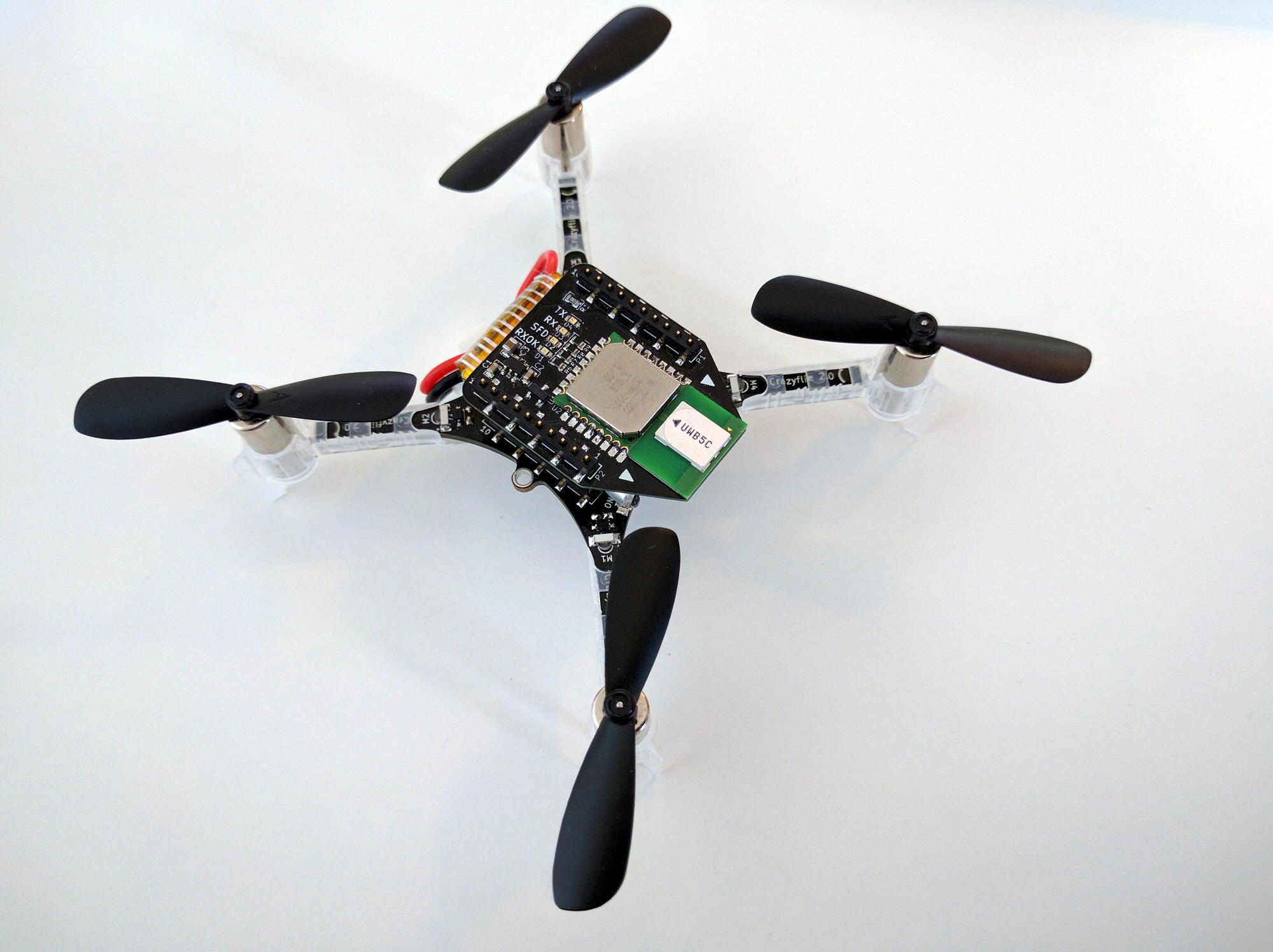
For now while Crazyswarm2 is still under development, I used the Bitcraze Crazyflie python library to make a more hackish node that just publishes exactly the information I want. I am focusing on the scenario with the STEM ranging bundle, aka the Crazyflie + Flowdeck (optical flow + distance sensor) + Multi-ranger (5 x distance sensors) combo, where the node logs the multi-ranger data and the odometry from the Flowdeck with the Crazyradio and outputs that into necessary /scan and /odom topics. Moreover, it also outputs several tf2 transforms that makes it possible to either visualize it in RVIZ and/or connect it to any other packages and it should react to incoming twist messages as well.
Development with a Simulator
And of course… I went in head first and connected it directly with the SLAM toolbox. I have worked with ROS1 in the past, but I had my first experience working with that package in the course: Build Mobile Robots with ROS2 (by Weekly Robotic Newsletter’s Mat Sadowski), so I couldn’t wait to try it on a real platform like the Crazyflie. However, tuning this was of course more work than I thought, as the map that I got out of it first was mostly a sparse collection of dots. Of course the SLAM toolbox is meant for lidars and not something that provided sparse range distances like the Multiranger. Then I decided to take one or two steps back, and first connect a simulator to make tuning a bit easier.
Luckily, I’ve already started to look at simulators, and was quite far in the Webots integration of the Crazyflie. Actually… Webots’ next release (2022b) will contain a Crazyflie as standard! Once it is out, I’ll write a blogpost about that separately :). As luck has it, Webots also has good ROS2 integration as well, and even won the ‘Best ROS Software’ award by The Construct’s ROS awards! Another reason is that I wanted to try out a different simulator for ROS2 this time to complement what I’ve learned in the ROS2 course I mentioned earlier.
So I used the webots driver node to write a simulated Crazyflie that should output the same information as the real Crazyflie node, so that I can easily hack around and try out different things without constantly disturbing my cats from their slumber :). Anyway, I won’t go into to the simulator too much and save that for another blogpost!
Simple Mapping
I decided to also take another additional step before going full SLAM, which is to make a simple mapper node first! This takes the estimated state estimate of the Crazyflie and the Multiranger’s range values and it creates an occupancy grid type map of it. I do have to give kudos to the Marcus’ cflib Pointcloud script and Webot’s simple mapper example, as I did look at them for some reference. But still with the examples, integration and connecting the dots together is quite some work. Luckily I had the simulator to try things out with!
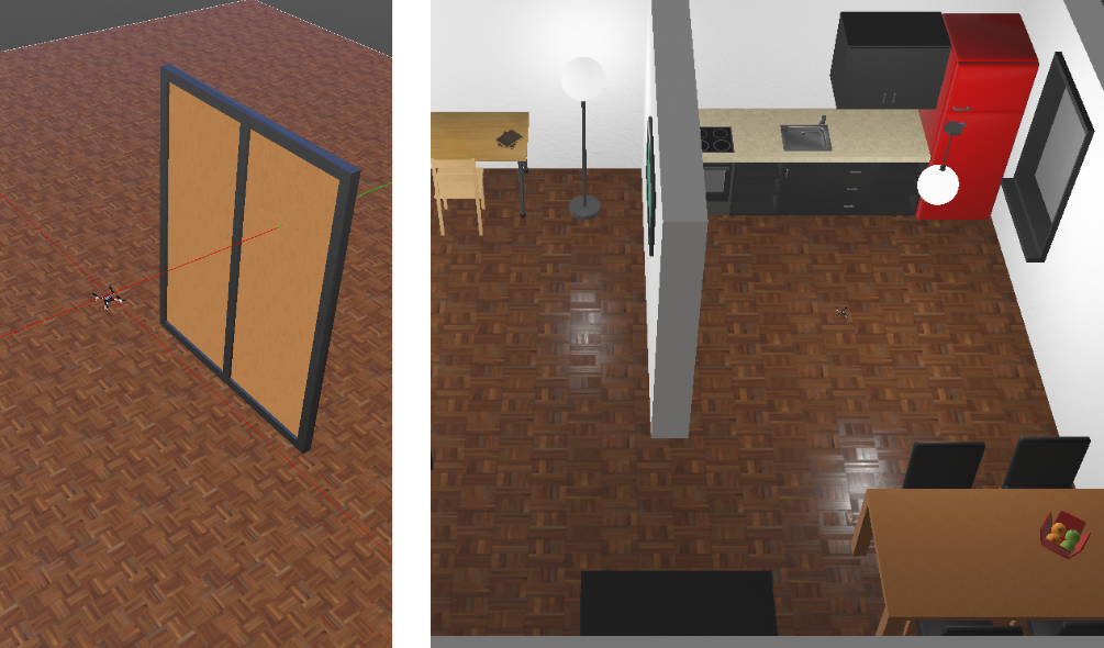
So first I put the Crazyflie in an apartment simulator, flew around and see if any decent maps comes out of it and it seemed it did! Of course, the simulated Crazyflie’s ‘odometry’ comes from near perfect position estimate, so I didn’t expect any problems there (and in such a situation you would actually not really need the localization part of SLAM). This still needs some improvements to be done, like now range measurements that don’t see anything are excluded from drawing, but still it was pretty cool to map the virtual environment.
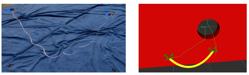
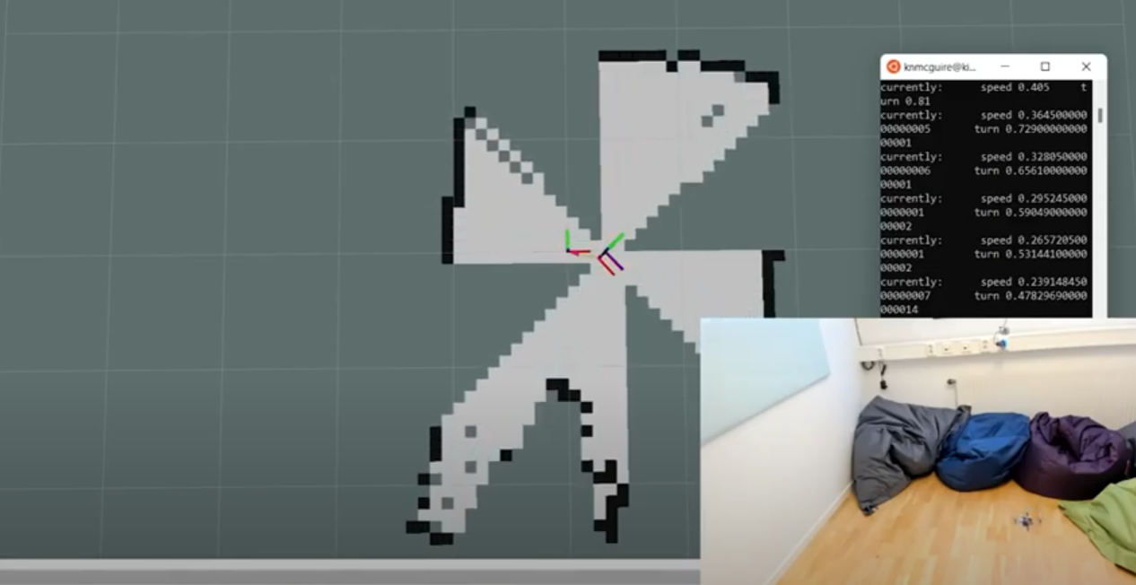
So it was off to try it out on a real crazyflie. In one of our meeting rooms, I had one Crazyflie take off, let it turn around with a twist message in a /cmd_vel topic and made a map of the room I was currently in. The effect of the 4 range sensors rotating around and creating a map in one go, makes me think of these retro video transitions. And the odometry drift does not seem as bad for it to be possible, but I haven’t mapped our entire office yet so that might be different!
What’s next?
So I’m not stopping here for sure, I want to extend this functionality further and for sure get it to work with the SLAM_toolbox properly! But if the simple mapper already can produce such quality, I’m pretty sure that this can be done in one way or the other. What I could also do, is first generate a simple map and already have a go at the NAV2 package with that one… there are many roads to Rome here!
Currently I’m doing my work on my personal Github account in the crazyflie_ros2_experimental repository. Everything is still very much in development, hackish and quite specific for one use case but that is expected to change once things are working better, so please check the planning in the project’s readme. In the mean time, you can indicate to us in this vote if this is an interesting direction for us to go towards. Not that it will stop me from continuing this project since it is too much fun, but it is always good to know if certain efforts are appreciated!