The Holiday season is already in full gear here, with Christmas lights everywhere, and even though it’s not going to be an usual celebration for many of us, we’re trying to find ways to make it memorable.
Our first thought for preparing the year to come (other than hoping for less dire circumstances worldwide) is to find out how we can better your experience.
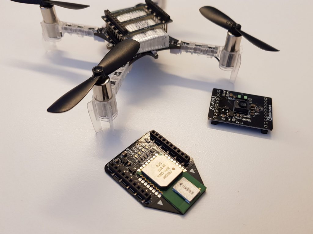
Since this summer, we’ve been wondering how to improve ourselves. We have made some great headways in stabilizing what we offer. Whether with our documentation (new step-by-step guides and online tutorials), our hardware (our new propellers work perfectly) or our software (a new client and app API), we tried to improve what we already have.
We pride ourselves in knowing our defaults, but we strive to correct them as much as we can. However, we’re aware that we’re not perfect, and have some blind spots. Be that as it may, improving ourselves means also knowing where there’s room for improvement! And that’s where you are needed.
We’d like to know your thoughts and feedback, and the best way to learn from you is to ask you questions. So we created a quick survey: it takes only 3 minutes to answer and would help us a lot. In fact, it will help us shape 2021, or at least the beginning of it, as we want to stabilize our portfolio and our documentation. The goal of the survey is to pinpoint the areas that need improvements and to gain general knowledge on our customers.
Click here if you want to help and answer the survey!
A Christmas party !
And, before we start 2021 with your feedback, we’d like to hear from you in real time! We’re indeed planning a Bitcraze Christmas gathering, on:
Day: Tuesday December 15th
Time: 17:00 Central European Time (Malmö, Sweden).
It would be nice to join us with some (virtual) mulled wine, to talk about the Crazyflie, or share some Christmas spirit together . We promise we won’t sing any Christmas carols, but maybe we can show some nice videos!
So join us on the Discord server where we will provide further information and open up a video&voice channel/Mozilla hubs room on the day itself.
This week we have a guest blog post from CollMot about their work to integrate the Crazyflie with Skybrush. We are happy that they have used the app API that we wrote about a couple of weeks ago, to implement the required firmware extensions!
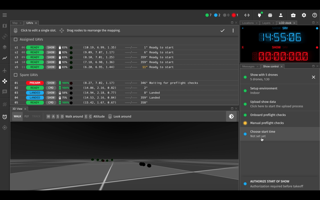
Bitcraze and CollMot have joined forcesto release an indoor drone show management solution using CollMot’s new Skybrush softwareand Crazyflie firmware and hardware.
CollMot is a drone show provider company from Hungary, founded by a team of researchers with a decade-long expertise in drone swarm science. CollMot offers outdoor drone shows since 2015. Our new product, Skybrush allows users to handle their own fleet-level drone missions and specifically drone shows as smoothly as possible. In joint development with the Bitcraze team we are very excited to extend Skybrush to support indoor drone shows and other fleet missions using the Crazyflie system.
The basic swarm-induced mindset with which we are targeting the integration process is scalability. This includes scalability of communication, error handling, reliability and logistics. Each of these aspects are detailed below through some examples of the challenges we needed to solve together. We hope that besides having an application-specific extension of Crazyflie for entertainment purposes, the base system has also gained many new features during this great cooperative process. But lets dig into the tech details a bit more…
UWB in large spaces with many drones
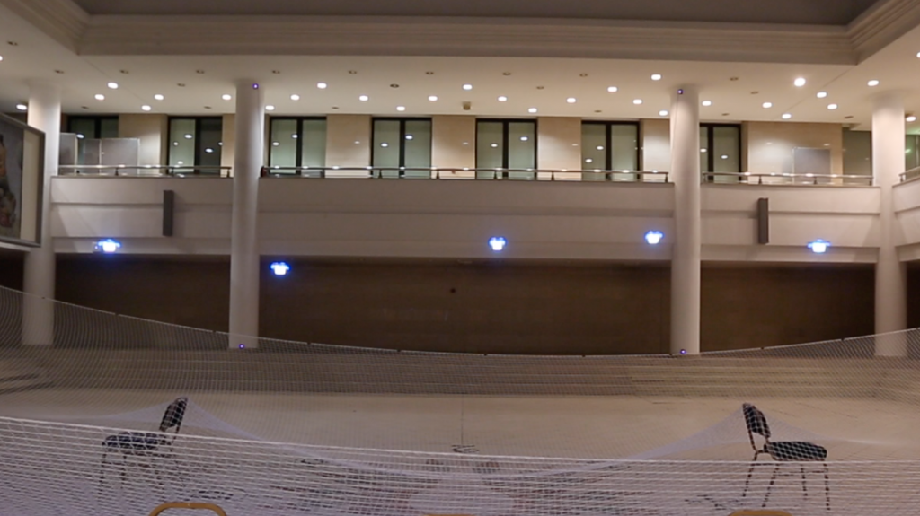
We have set up a relatively large area (10x20x6 m) with the Loco Positioning System using 8 anchors in a more or less cubic arrangement. Using TWR mode for swarms was out of question as it needs each tag (drone) to communicate with the anchors individually, which is not scalable with fleet size. Initial tests with the UWB system in TDoA2 mode were not very satisfying in terms of accuracy and reliability but as we went deeper into the details we could find out the two main reasons of inaccuracies:
Two of the anchors have been positioned on the vertical flat faces of some stairs with solid material connection between them that caused many reflections so the relative distance measurements between these two anchors was bi-stable. When we realized that, we raised them a bit and attached them to columns that had an air gap in between, which solved the reflection issue.
The outlier filter of the TDoA2 mode was not optimal, a single bad packet generated consecutive outliers that opened up the filter too fast. This issue have been solved since then in the Crazyflie firmware after our long-lasting painful investigation with changing a single number from 2 to 3. This is how a reward system works in software development :)
After all, UWB was doing its job quite nicely in both TDoA2 and TDoA3 modes with an accuracy in the 10-20 cm level stably in such a large area, so we could move on to tune the controller of the Crazyflie 2.1 a bit.
Crazyflies with Loco and LED decks
As we prepared the Crazyflie drones for shows, we had the Loco deck attached on top and the LED deck attached to the bottom of the drones, with an extra light bulb to spread light smoothly. This setup resulted in a total weight of 37g. The basic challenge with the controller was that this weight turned out to be too much for the Crazyflie 2.1 system. Hover was at around 60-70% throttle in average, furthermore, there was a substantial difference in the throttle levels needed for individual motors (some in the 70-80% range). The tiny drones did a great job in horizontal motion but as soon as they needed to go up or down with vertical speed above around 0.5 m/s, one of their ESCs saturated and thus the system became unstable and crashed. Interestingly enough, the crash always started with a wobble exactly along the X axis, leading us to think that there was an issue with the positioning system instead of the ESCs. There are two possible solutions for this major problem:
use less payload, i.e. lighter drones
use stronger motors
Partially as a consequence of these experiments the Bitcraze team is now experimenting with new stronger models that will be optimized for show use cases as well. We can’t wait to test them!
Optimal controller for high speeds and accurate trajectory following
In general we are not yet very satisfied with any of the implemented controllers using the UWB system for a show use-case. This use-case is special as trajectory following needs to be as accurate as possible both in space and time to avoid collisions and to result in nice synchronized formations, while maximal speed both horizontally and vertically have to be as high as possible to increase the wow-effect of the audience.
The PID controller has no cutoffs in its outputs and with the sometimes present large positioning errors in the UWB system controller outputs get way too large. If gains are reduced, motion will be sluggish and path is not followed accurately in time.
The Mellinger and INDI controllers work well only with positioning systems of much better accuracy.
We stuck with the PID controller so far and added velocity feed forward terms, cutoffs in the output and some nonlinearity in case of large errors and it helped a bit, but the solution is not fully satisfying. Hopefully, these modifications might be included in the main firmware soon. However, having a perfect controller with UWB is still an open question, any suggestions are welcome!
Show specific improvements in the firmware
We implemented code that uploads the show content to the drones smoothly, performs automatic preflight checking and displays status with the LED deck to have visual feedback on many drones simultaneously, starts the show on time in synchrony with all swarm members and handles the light program and show trajectory execution of the show.
These modifications are now in our own fork of the Crazyflie firmware and will be rewritten soon into a show app thanks to this new promising possibility in the code framework. As soon as Skybrush and Crazyflie systems will be stable enough to be released together, we will publish the related app code that helps automating show logistics for every user.
Summary
To sum it up, we are very enthusiastic about the Crazyflie system and the great team behind the scenes with very friendly, open and cooperative support. The current stage of Crazyflie + Skybrush integration is as follows:
New hardware iterations based on the Bolt system that support longer and more dynamic flights are coming;
a very stable, UWB-compatible controller is still an open question but current possibilities are satisfying for initial tests with light flight dynamics;
a new Crazyflie app for the drone show case is basically ready to be launched together with the release of Skybrush in the near future.
If you are interested in Skybrush or have any questions related to this integration process, drop us an email or comment below.
As many European countries, Sweden is now suffering the effects of the second COVID-19 wave. In line with current local restrictions we’re limiting the number of people at our office, which for us means no external guests and only a few people at a time. Although for customers there won’t be any difference since we’re still keeping our regular shipping (1-2 days after placing the order).
Stock levels
During the next couple of weeks we’re going to be short on some of our products, specifically the Swarm bundle, Loco Positioning deck and AI deck. We’re working hard to get them back into stock, and they are scheduled to arrive first weeks of December.
Lighthouse progress
Lately we have been working on finalizing the support for two lighthouse base stations (V1 as well as V2) in the firmware and python lib, which means that we are messing around with large portions of the lighthouse code. As some of you may have noticed it also means that the code base is unstable from time to time. It is likely that it will take a couple of more weeks before it settles down and it might be a good idea to avoid the latest commit if you are looking for a fully working and documented system. Hopefully we will have a good base for future releases and functionality when we are done.
The latest official stable release is 2020.09 and this is also what we recommend for now.
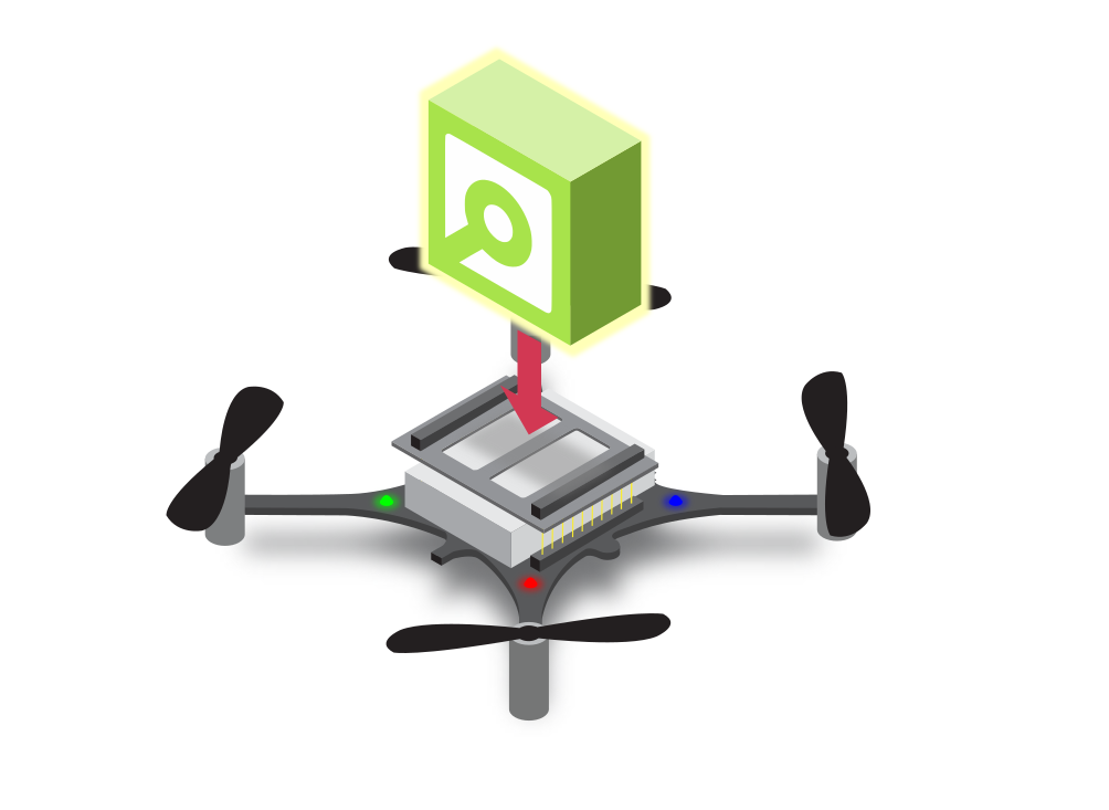
As mentioned in this blog post, we added the possibility to write apps for the Crazyflie firmware a while ago. Now we have added more functions in the Firmware to make it possible to use apps for an even wider range of tasks.
The overall idea of the app API is to mirror the functionality of the python lib. This will enable a user to prototype an application in python with quick iterations, when everything is working the app can easily be ported to C to run in the Crazyflie instead. The functions in the firmware are not identical to the python flavour but we have tried to keep them as close as possible to make the translation simple.
An app is also a much better way to contain custom functionality as the underlying firmware can be updated without merging any code. The intention is that the api API will be stable over time and apps that work one version of the firmware also should work with the next version.
Improvements
We used our demo from IROS and ICRA (among others) with a fairly autonomous swarm as a driver for the development. The demo used to be implemented in a branch of the firmware with various modifications of the code base to make it possible to do what we wanted. The goal of the exercise was to convert the demo into an app and add the required API to the firmware to enable the app to do its thing. The new app is available here.
The main areas where we have extended the API are:
Log and parameters framework
The log framework is the preferred way for an app to read data from the firmware and this has been working from the start. Similarly the parameter framework is the way to set parameters. Even though this has worked, it broke a basic assumption in the setup with the client, that only the client can change a parameter. Changing a parameter from an app could lead to that the client and Crazyflie had different views of the state in the Crazyflie, but this has now been fixed and the client is updated when needed.
High level commander
The high level commander was not accessible from an app earlier and the functions in the python lib have been added to make it easy to handle autonomous flight.
Custom LED sequences
It is now possible to register custom LED sequences to control the four LEDs on the Crazyflie to signal events or state.
Lighthouse functionality
Functions for setting base station geometry data as well as calibration data have been added. These functions are also very useful for those who are using the lighthouse system as it now can be done from an app instead of modifying lighthouse_position_est.c.
Remaining work
We have taken a step forward with these changes but there is more to be done! The two main areas are support for custom CRTP packets and memory mapping through the memory sub system. There might be more, let us know if there is something you are missing. The work will continue and there might even be some documentation at some point :-)
Tutorial
One reason for doing this API work now was to prepare for the tutorial about the lighthouse 2 positioning system, swarm autonomy and the demo app that we will run this Wednesday on-line, don’t miss out! You can read more about the event here.
Back in 2014 a friend of ours dropped by our office to chat a bit about how things were going for Bitcraze. During the conversation we got a few questions that we should have been able to answer, but we couldn’t. Things like “How many Crazyflies have you sold?” and “To which countries do you mostly sell?”. We realized that we need some way of keeping track of things like this. Since I was mostly handling economics and admin, and also like developing things, this became the start of our internal “do a bit of everything” system.
At this point in time we were only selling our products though Seeedstudio, so the system was mostly used to keep track of the stock levels there. But as things at Bitcraze started to change, so did the system. Later that year our Crazyflie 2.0 was heading into production and we wanted a better way to keep track of production, so we modified the production scripts to upload the production test results to our servers. Now we had production stats and could trace returns from the field trough production using serial numbers.
Fast forward to 2016 and we’ve decided to start selling our products in our own E-store. We found a 3PL partner in Hong Kong to do our packaging and shipping. It was a big step for us and something we really liked since we got direct contact with our customers. But the amount of work quickly started to increase. Our main issue was that some customers were not keeping track of their shipments and the shipments would end up sitting in customs awaiting questions from the customers and would eventually be returned to us, and this was a big hassle. So the tracking of orders were added to our internal system, now it would keep track of the shipment progress and warn us if there were any issues.
Apart from the E-store we also had orders though our invoicing software. In order for us to get a unified picture of what was happening our internal system started to merge information from the different systems: our E-store, invoicing software and Seeedstudio.
At this point the system had grown so much that the architecture was a bit out of hand and we re-wrote the system from scratch to be able to handle more changing requirements. In hindsight was a good decision, since the next big change change was around the corner. In 2018 everything was running smoothly but our 3PL partner was suddenly moving the warehouse from Hong Kong to Shenzhen (blog post), something that was supposed to take a week and run smoothly. Unfortunately the move was everything else than smooth and after battling for months trying to get the operation back up again, we finally pulled the breaks and started to re-route newly produced units to our office in Sweden instead.
Now we had an office full of products and an E-store were things were being sold. But we didn’t have any solution for actually taking the orders and shipping them. At first we were booking everything manually, but as order counts increased this quickly became a problem. We looked at a few solutions but didn’t find anything that matched well for integrating all our systems. So our internal system once again got expanded to handle the warehouse part, print packing lists, book shipments and print labels (blog post).
As time passes (and more challenges pop up) we’ve been adding more and more functionality and have been able to quickly adapt to what’s been happening. While developing the system over the years, my overall goal has been to automate as much as possible of the admin/logistics in order to keep the workload the same even though sales increase. So far this has been successful!
Today we use this system for a wide range of administration, logistics and production tasks. Below is a list of some of the things it handles:
Keep track of all tested units with all data from the tests
Production planning and warning if things will run out of stock
Analytics
Various harmonized business analytics from our different sales systems
Harmonized data that is used for various analysis
Reminds us about various things like unpaid invoices
So have we made back the time we spent building the system? Probably not, but we will. There’s a lot of good solutions for similar systems out there, but the decision to make our own system came from not finding a solution where all our pieces fit. In order to minimize the work I’ve tried to use various external services to speed up development. In the end the list of systems that are used together is quite long:
Our production test software
Shopify (E-store SaaS)
Fortnox (Bookkeeping, invoicing and quoting SaaS)
Easypost (shipping API)
Riksbanken (for exchange rates)
Our printing station software for label/document printers
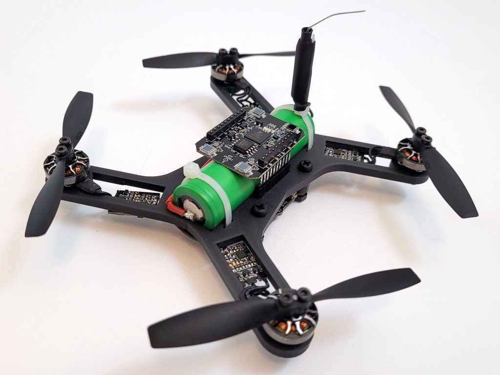
Li-Ion batteries have packed more energy per gram for a long time compared to Li-Po batteries. The problem for UAV applications has been that Li-Ion can’t deliver enough current, something that is starting to change. Now there are cells that are supposed to be able to deliver 30-35A continuously in the 18650 series, at least according to the specs. Therefor we thought it was time to do some testing and decided to build a 1 cell Li-Ion drone using the Crazyflie Bolt as base.
Since a 18650 battery is 18mm in diameter and 65mm long, the size would affect the design but we still wanted to keep the drone small and lightweight. The battery is below 20mm wide which means we can run the deck connectors around it, that is nice. We chose to use our 3D printer to build the frame and use off the shelf ESCs, motors and props. After a couple of hours of research we selected 3″ propellers, 1202.5 11500kv motors and tiny 1-2s single ESCs for our first prototype.
Parts list:
1 x Custom designed 130mm 3D printed frame
1 x Crazyflie Bolt flight controller
4 x Eachine 3020 propeller (2xCW + 2xCCW)
4 x Flywoo ROBO RB 1202.5 11500 Kv motors
4 x Flash hobby 7A 1-2S ESC
1 x Li-Ion Sony 18650 VTC6 3000mAh 30A
Screws, anti vib. spacers, zipties, etc.
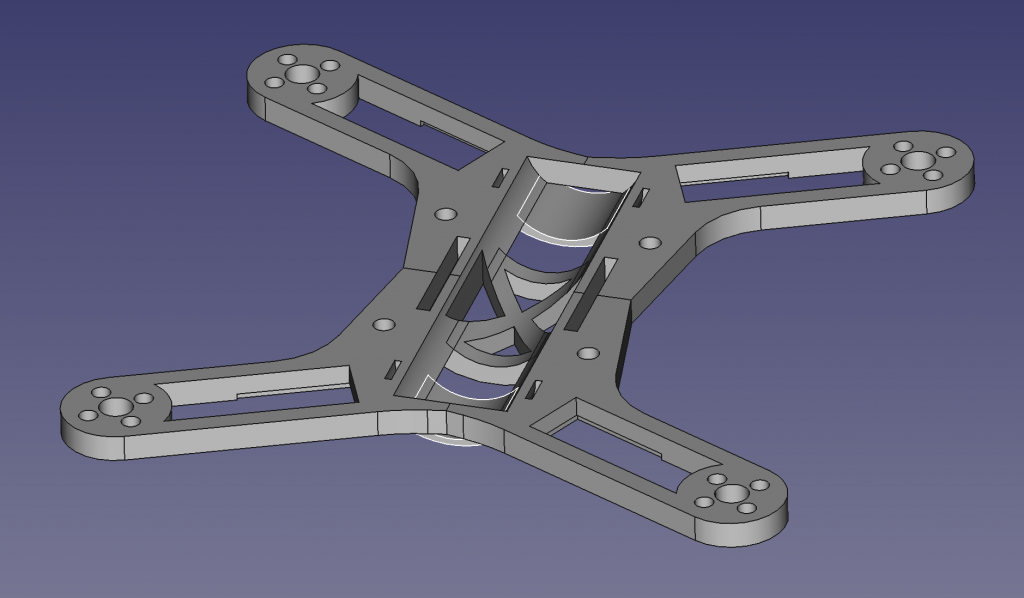
The custom designed frame was developed in iterations, and can still be much improved, but at this stage it is small, lightweight and rigid enough. We wanted the battery to be as central as possible while keeping it all compact.
Prototype frame designed in FreeCAD.
Assembly and tuning
The 3D printed frame came out quite well and weighed in at 13g. After soldering the bolt connectors to the ESCs, attaching motors and props, adjusting battery cable and soldering a XT30 to the Li-Ion battery it all weighed ~103g and then the battery is 45g of these. It feels quite heavy compared to the Crazyflie 2.1 and we had a lot of respect when we test flew it the first time. Before we took off we reduced the pitch and roll PID gains to roughly half and luckily it flew without problems and quite nicely. Well it sounds a lot but that is kind of expected. After increasing the gains a bit we felt quite pleased with:
This would be good enough for what we really wanted to try, the endurance with a Li-Ion battery. A quick measurement of the current consumption at hover, 5.8A, we estimated up to ~30 min flight time on a 3000mAh Li-Ion battery, wow, but first a real test…
Hover test
For the hover test we used lighthouse 2 which is starting to work quite well. We had to change the weight and thrust constants in estimator_kalman.c for the autonomous flight to work:
#define CRAZYFLIE_WEIGHT_grams (100.0f)

//thrust is thrust mapped for 65536 <==> 250 GRAMS!
#define CONTROL_TO_ACC (GRAVITY_MAGNITUDE*250.0f/CRAZYFLIE_WEIGHT_grams/65536.0f)
After doing that and creating a hover script that hovers at 0.5m height and was set to land when the voltage reached 3.0V. We leaned back with excitement, behind a safety net, and started the script… after 19 min it landed… good but not what we hoped for and quite far from the calculated 30 min. Maybe Li-Ion isn’t that good when it needs to provide more current…? A quick internet search and we could find that Li-Ion can run all the way down to 2.5V, but we have to stop at 3.0V because of electronics and loosing thrust, so we are missing quite a bit of energy… Further investigations are needed.
Lighthouse 2 flight test
As a final test we launched some flight scripts to fly in a square and in a spiral so we would get a feel for Lighthouse 2 + Bolt with PID controller combination. We think it turned out quite nicely, and this with almost no optimization effort:
Summary
Li-Ion felt like it could be a game changer when it comes to flight time but was not as promising as we hoped for. It doesn’t mean we can’t get there though. More research and development is required.
During the summer we were discusses at the office of what would be a good substitute of us not being able to go to conferences or fairs anymore (see this blogpost). We sparred with a few ideas, ranging from organizing an online competition to an seminar. Although we initially were quite enthusiastic about organizing the competition, the user questionnaire from the previous blog-post showed us that many of you are rather interested in online tutorials. Based on that we actually started to make some more step-by-step guides, however we definitely would agree that is not the same as meeting each-other face-to-face!
So now we are planning to organize one for real this time! So our first online live tutorial will be on:
Wednesday 4th of November, 18:00 (CET, Malmö Sweden)
Register for the first session here to indicate your interest and to receive up-to-date information. There are of course no cost involved!
First topic: Spiraling Swarm Demo (Live!)
The last couple of years we have been showing our demo at many robotics conferences and fairs, such as ICRA, IMAV and IROS. Since we do not have a opportunity to do that anymore (at least for the foreseeable future), we thought that a suitable first topic of the online tutorial to be about the Spiraling Swarm demo! We will go through the different elements of the demo, which includes the implementation details on the Crazyflie and the Lighthouse Positioning system. We hope to explain all of in about 20-30 minutes and that this would enable you to set the demo up yourself if you want.
We have been thinking about just doing a prerecorded tutorial, however we also really like to talk with our users about their needs and research topics. That is why we think it is important to do it live where we can answer your questions on the go or after the tutorial. This also means that we will be demonstrating the demo live as well! Afterwards we will have a social interaction where we have a friendly chat :)
Mozilla Hubs and Discord
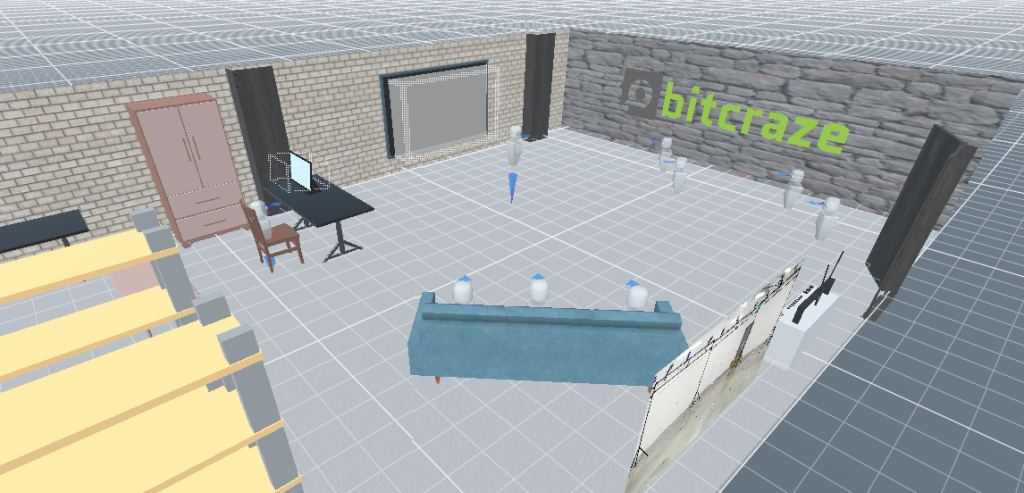
There are so many options on how to exactly host this event, as there are a gazillion alternatives for video conferencing. Currently we have are looking at Mozilla hubs. which fits nicely with our interests in the lighthouse positioning system with the HTC Vive basestations. The nice thing aspect of Hubs is that you don’t need a fancy headset to join, since it is possible to join via your browser or your phone. Me (Kimberly) has joined a Virtual Reality seminar at the beginning of the pandemic, organized by Roland Meertens of pinchofintelligence.com, and it was definitely a very interesting and fun experience. When giving a presentation, it really felt like people were paying attention and were engaged. So, we recently recreated our own flight-lab in VR (using Hub’s environment creator Spoke) and tested it out ourselves. This way you will be able to see our workplace as well!
Of course, we can imagine not everybody is waiting to go full VR. That is why we will combine the online tutorial with Discord, where we will make a video channel where we will stream the live demo and tutorial. It will also be possible to send messages that are visible in both the VR space and the Discord chat channel with Hub’s discord bot. You can choose where to follow the tutorial — fully in VR, or first discord and afterwards socialize in VR — that is totally up to you.
We still need to figure out the specifics, but if you register with your email we will send all the necessary information for the first session to you directly.
IOT conference Malmö
Now something else: tomorrow, namely Tuesday the 5th of October, we will also present at the IOT conference 2020 in Malmö. It is free for participants and it is still possible to register! Come and join if you can not wait to see us until the 4th of November.
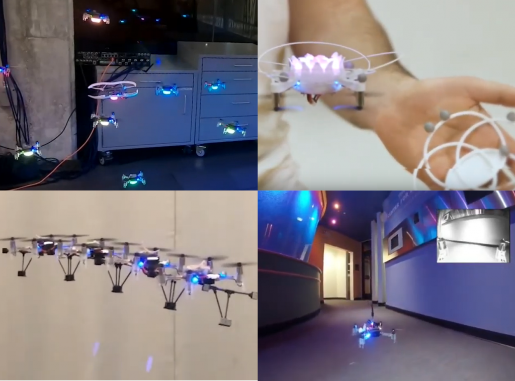
It has almost been 2.5 years since we last made a compilation video about what has been done with the crazyflie 2.0 (see this blogpost). During this time we released several new products and many of you were able to achieve very cool and awesome applications so we thought it was time for a new research compilation video!
We have seen quite a lot of projects with swarms of Crazyflies, ranging from close proximity flight to autonomous exploration in a building. Some research groups have also been experimenting with controlling the Crazyflie with our own hands, either to control its position or to reach another state of mind entirely. Others have created their own deck in order to add their own sensors or cameras necessary for their application. One of those even led to the new AI-deck that we introduced in early release before the summer! Last but not least: we were shown that the low level control can be further improved and multiple crazyflies can be linked together and still fly!
We were overwhelmed by all the awesome things that the community showed us of what possible with the Crazyflie and this will inspire others to think of new things to do as well. We hope that we can continue with helping you to make your ideas fly, so that we are soon to be forced to make another completion video ;)
Here is a list of all the research that has been included in the movie:
Close proximity flight of sixteen quadrotor drones, CalTech: B. Rivière, W. Hoenig, Y. Yue, and S.-J. Chung (video, paper)
Pointing gestures, IDSIA: B. Gromov, J, Guzzi, L. M. Gambardella, A. Giusti (video, project)
Yaw actuation, Modlab UPenn: B. Gabrich G. LiM. Yim (video, paper)
Learning to seek, Harvard University: B. P. Duisterhof , S. Krishnan, J. J. Cruz, C. R. Banbury, W. Fu, A. Faust, G. C. H. E. de Croon, V. Janapa Reddi (video, paper)
Drone Chi, Exertion Labs and RMIT: J. La Delfa, M. Baytas, E. Luke, B. Koder, F. Mueller (video, project)
Generalization through simulation, Berkeley AI Research (BAIR): K. Kang, S. Belkhale, G. Kahn, P. Abbeel, S. Levine (video, paper)
Swarm exploration, TU Delft: K.N. McGuire, C. De Wagter, K. Tuyls, H. Kappen, G.C.H.E. de Croon (video, paper)
PULP-based autonomous drone, ETH Zürich: D. Palossi, F. Conti, and L. Benini (video, paper)
Networked Autonomous Aerial Vehicles, University of Klagenfurt, Austria: Research by Karl Popper Kolleg (video)
GLAS for Multi-Robot Motion Planning with End-to-End Learning, CalTech: B. Rivière, W. Hoenig, Y. Yue, and S.-J. Chung (video, paper)
Resilience by reconfiguration, USC: R. K. Ramachandran, J. A. Preiss, G. S. Sukhatme (video, paper)
We are happy to annouce that we have released a new version of the Crazyflie firmware, version 2020.09. It is available for download from Github.
The new firmware solves an old compatibility issue when using the LPS and Flow deck at the same time and also improves stability. A list of all the issues that have been fixed can be found on the release page.
For users that have a LPS system, we have also made some improvements to the LPS node firmware and are releasing version 2020.09.
If you are building the Crazyflie or LPS firmware from source, remember to update the libdw1000 git submodule using
git submodule update
We are working on a release of the python client as well, but still have a few issues to fix so stay tuned.
It’s been more than 6 months now that I’ve joined Bitcraze and we are currently looking for more passionate people to join our team. So what is it like to work at Bitcraze? Here is my story.
First weeks
My first day of work was actually during one of our quarterly meetings, which means it was during a conference, in a good hotel with a nice spa and dinner, well needed after many hours of retrospective, brainstorming and planning. It was the perfect way to enter the Bitcraze world, and get to know my colleagues: it included serious talks, but also massages and board games. Did I get used to the good life? Well, I discovered that it was not all champagnes and jaccuzi: my first actual day at the office, I cut my finger pretty badly, spreading blood all over the kitchen. That’s fine, now everyone knows I’m not to be trusted with a knife! And I have a nice “Bitcraze” scar to show.
The on boarding itself included some education from our process guru, Kristoffer. I was excited and very curious to discover how a self-organizing company functioned, and I learned a lot during those sessions. I discovered a new way of working. It got some getting used to, but I got to really analyze and question my working habits and reflexes, which is always healthy. I am now an adept of lean and agile processes, and love being involved in the innerworking of the company and its processes.
Daily habits
As the days went along, I took my marks. I am everyday happy to get up and go to work. I especially love Mondays, that usually involve a nice morning chat, sitting on the sofa, discussing how the weekend was or the latest Netflix documentary, before beginning our weekly meeting. I discovered that Bitcraze is all about habits and routines, that I sometimes had to adapt to my non-geeky role. Tuesday for examples is usually dedicated to coding and programming: for me, it meant that’s the day I dig into the accounting!
We also have a tradition of “fun friday” that I really enjoy. The concept is simple: Fridays are dedicated to something that we love and have fun with. It allowed me to play around with my Crazyflie and its various decks, but also to work on my photographic skills or think about a more dedicated marketing strategy. It helps that usually, Fridays end with a nice chat around a beer and some VR games.
I love that I’ve got an independence to decide how my day is going to look like. My daily tasks include a lot of different things and areas. It’s a real luxury to me to be able to choose what I feel like tackling at any point. If I don’t feel like crunching numbers, I can deal with the shipments. Maybe today I’ll order those office supplies we need, or look into our social media statistics. When I first got recruited, the word “passion” came back a lot, and it didn’t disappoint: everything we do is driven by passion. I get to do and learn a lot of different things, and rarely get bored.
Global pandemic
Unfortunately, just as I begun to be comfortable on my new everyday routine, the world was hit by a global pandemic. Our habits were completely changed as we closed the door on the office and worked from home for 3 months.
I am actually really proud of how we handled it. Sure, the process and work flow changed drastically, but we kept on going, having faith in each other and in our capability in handling it. We kept the communication channels open, and produced the AI deck while working remotely.
For me, those times were though. I still needed the everyday guidance of my colleagues, which is trickier when they’re not sitting next to you. But it also gave me the opportunity to do more by myself, which ultimately led to learn things a lot quicker, I think. The hardest, though, was when everybody got to get back to the office, and I couldn’t: I belong in a risk group for Covid. I miss the fika with my colleagues, and working remotely seem pretty lonely.
Working as a non-tech
The trickiest part for everyone when I joined Bitcraze was to fit in the more technical aspects of the company. I only have a little programming and tech background, so including me in the geek discussions without using too much jargon was not easy for the guys. I learned a lot, in a short time. I still bug them with my questions and have a long list of terms and concepts I need to read about. But that’s ok, because my “cluelessness” actually provided good insights on the work we still have to do on documentation. And the work to understanding each other better actually flowed both ways: I had also sometimes to include my colleagues in more administrative aspects that they don’t know, or don’t care about. It’s interesting to try to adapt the Bitcraze process just because I’m here: it’s not only about developing tech anymore, we have to think about a way to involve administrative tasks to our methods.
All in all, working at Bitcraze is everything I thought it will be, and more: I love spending time with my colleagues. Each morning, I feel lucky to have joined a passionate and exciting company. I didn’t think I’ll be someone that happily turns her computer on a Sunday night to check what Monday will have to offer, but that’s what I end up doing most of the weeks.
That’s why my feelings today are mixed: I’m actually leaving the office to enjoy my generous Swedish maternity leave. Being pregnant and welcoming a new life is exciting, and I’m really happy to extend my family, but not working at Bitcraze will feel weird and I know I will miss it. Nevertheless, I know the guys will do fine without me, and I’ll be back in 2021 for more exciting news!
And if you’re interested in working at Bitcraze too, you’ll find more infos here !