This week we have a guest blogpost by Kamil Masalimov (MSc) and Tagir Muslimov (PhD) of the Ufa University of Science and Technology. Enjoy!
As researchers passionate about UAV technology, we are excited to share our recent findings on how structural defects affect the performance of nano-quadcopters. Our study, titled “CrazyPAD: A Dataset for Assessing the Impact of Structural Defects on Nano-Quadcopter Performance,” offers comprehensive insights that could greatly benefit the Crazyflie community and the broader UAV industry.
The Motivation Behind Our Research
Understanding the nuances of how structural defects impact UAV performance is crucial for advancing the design, testing, and maintenance of these devices. Even minor imperfections can lead to significant changes in flight behavior, affecting stability, power consumption, and control responsiveness. Our goal was to create a robust dataset (CrazyPAD) that documents these effects and can be used for further research and development.
Key Findings from Our Study
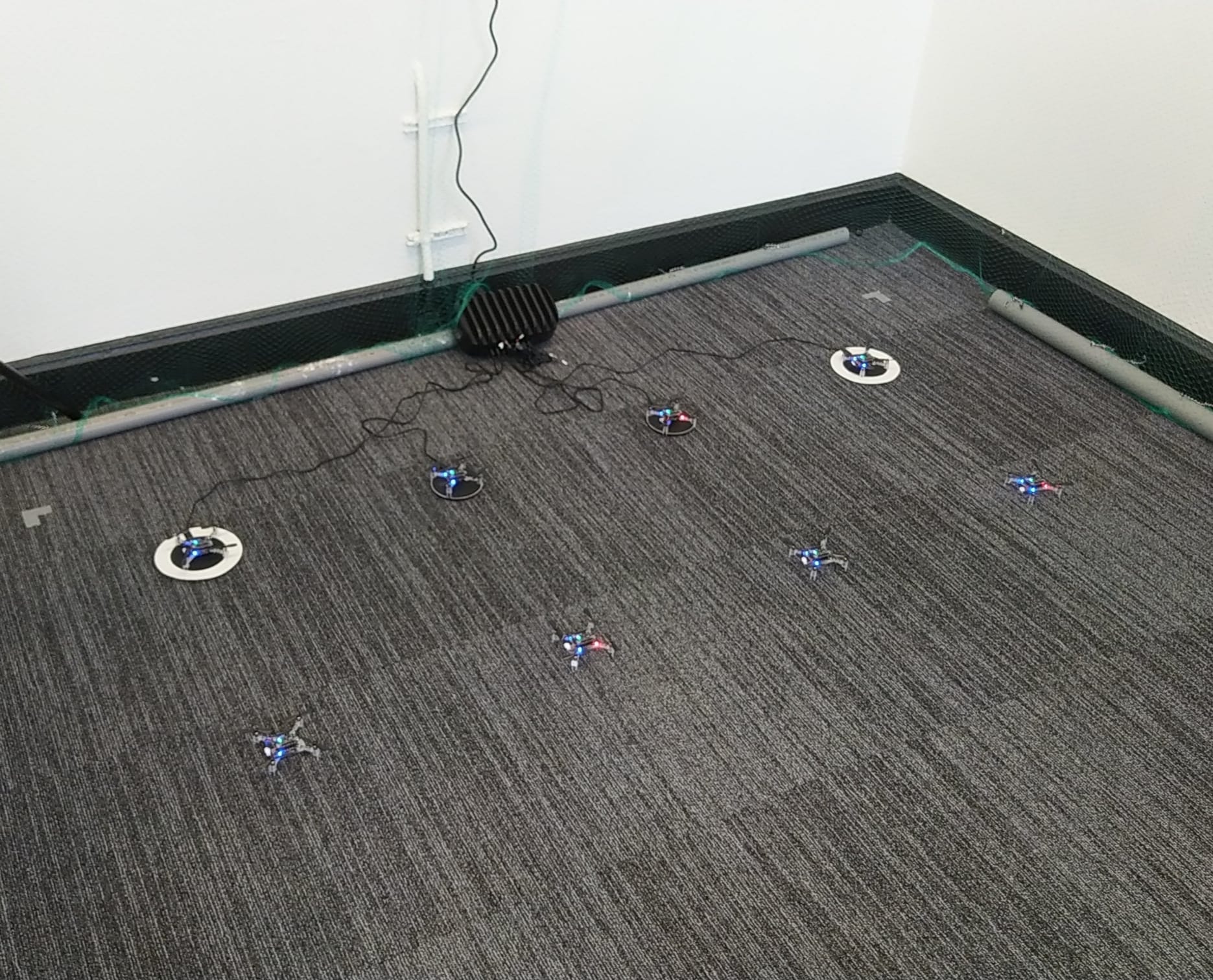
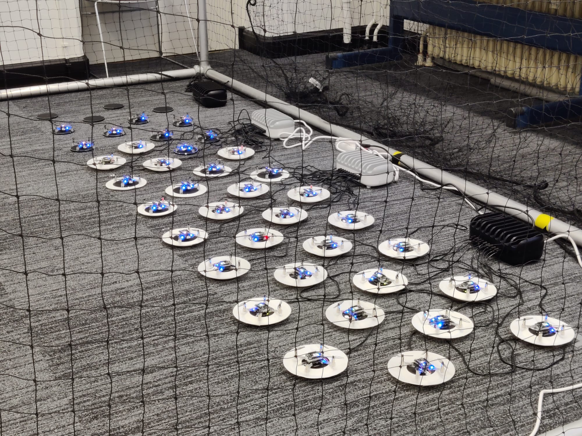
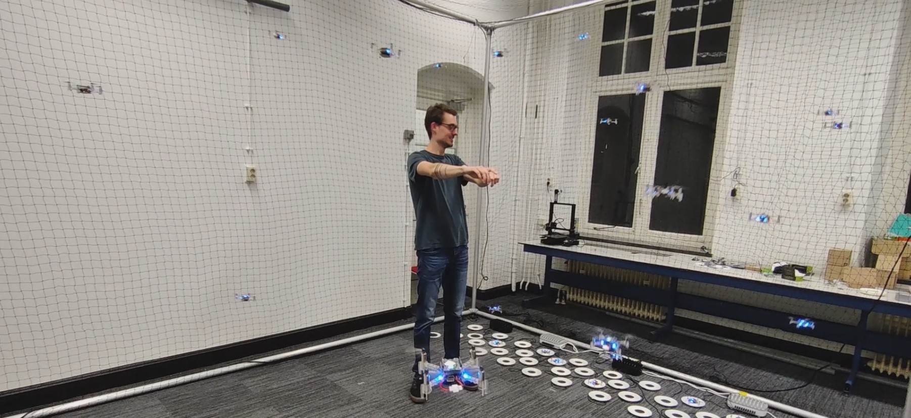
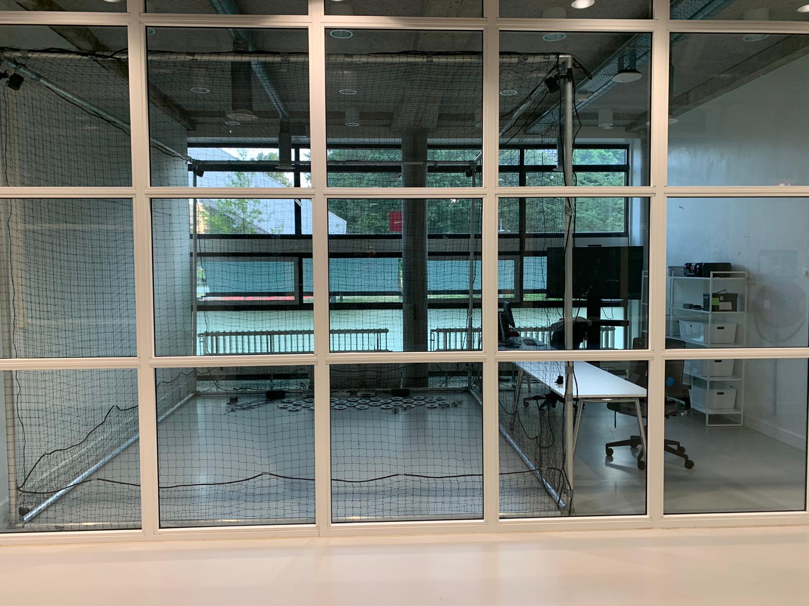
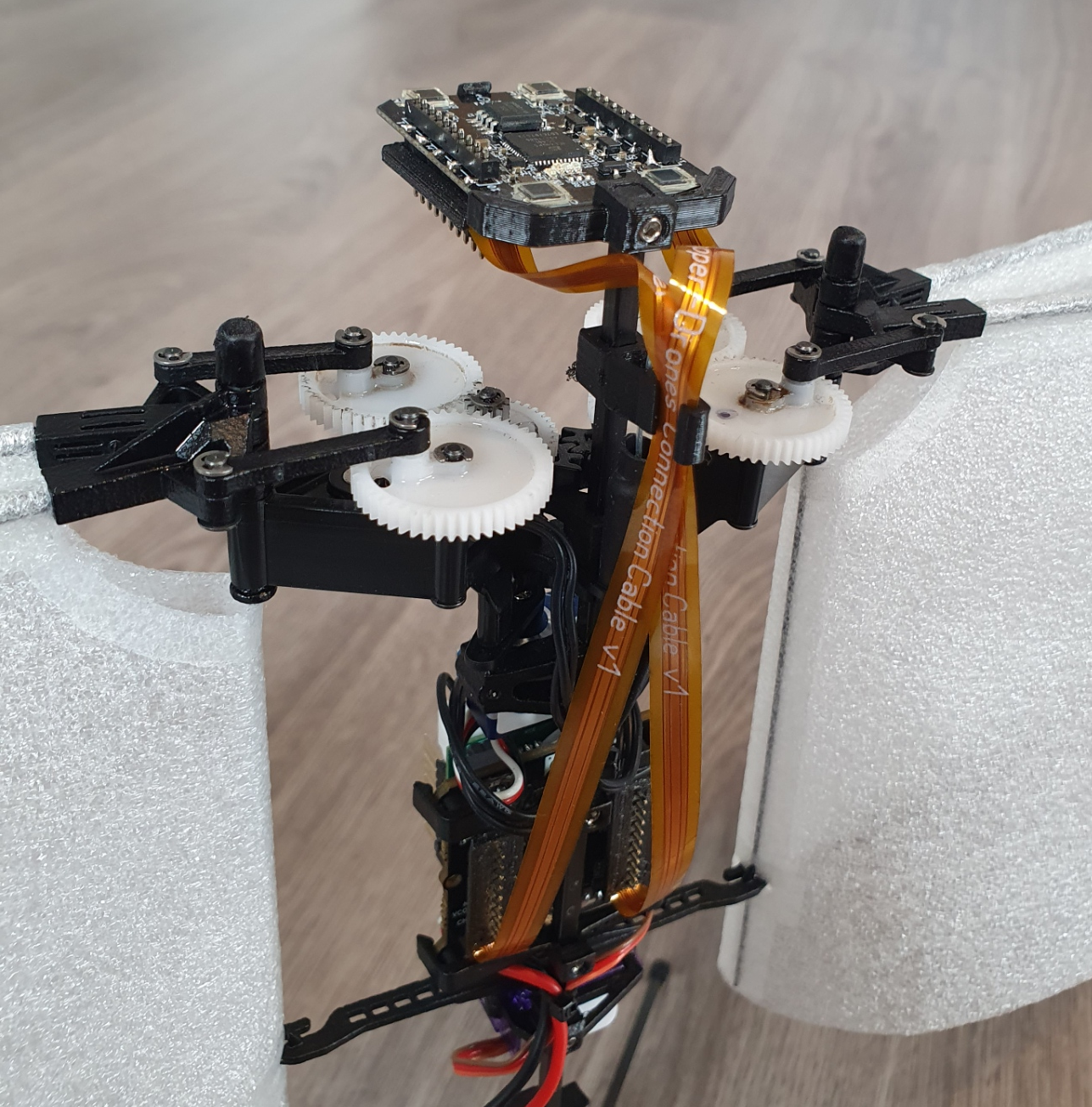
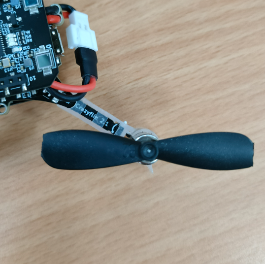
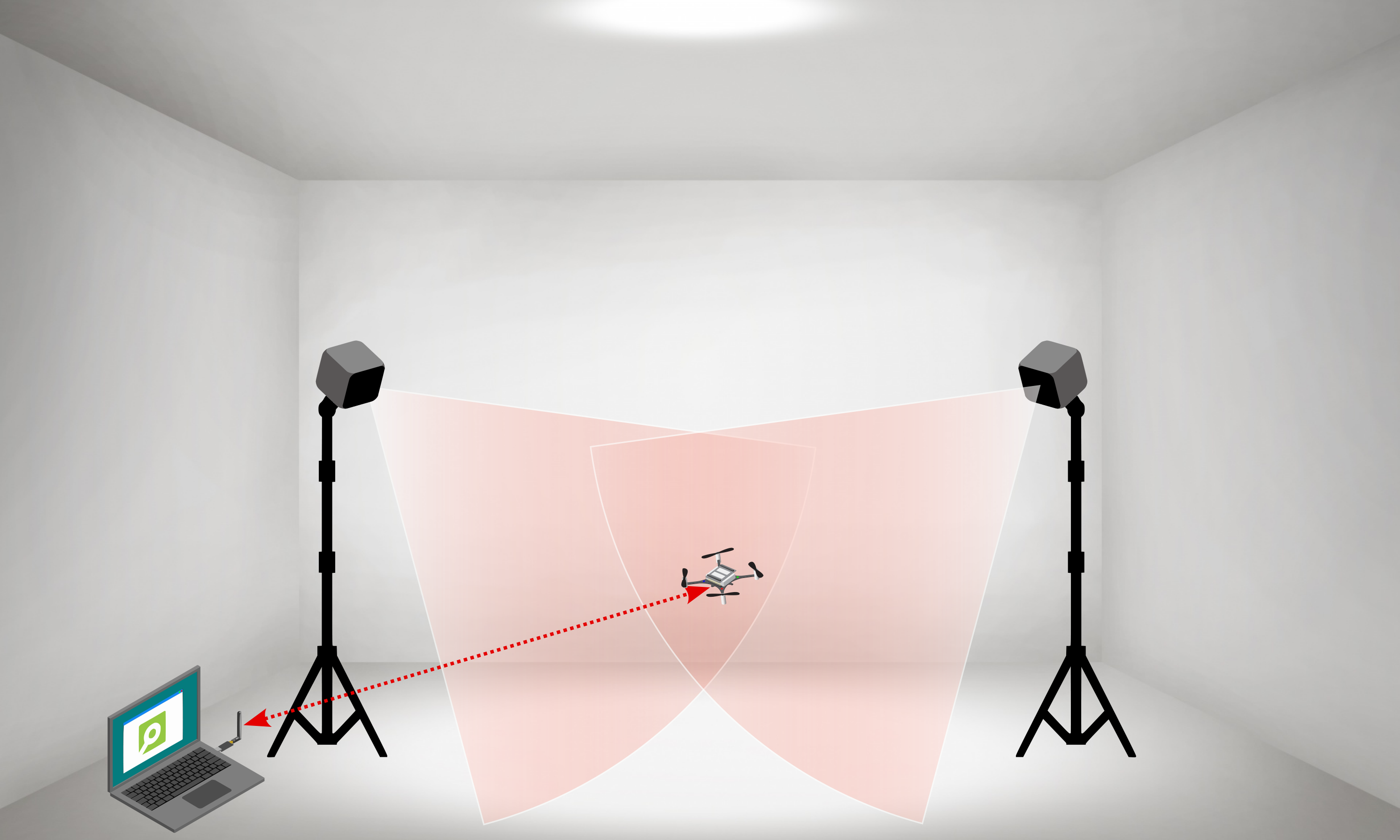
We conducted a series of experiments by introducing various defects, such as added weights and propeller cuts (Figure 1), to nano-quadcopters. For the experiments, we used the Lighthouse Positioning System with two SteamVR 2.0 virtual reality stations (Figure 2).
Here are some of the pivotal findings from our research:
- Stability Impact: We observed that both added weights and propeller cuts lead to noticeable changes in the stability of the quadcopter. Larger defects caused greater instability, emphasizing the importance of precise manufacturing and regular maintenance.
- Increased Power Consumption: Our experiments showed that structural defects result in higher power consumption. This insight is vital for optimizing battery life and enhancing energy efficiency during flights.
- Variable Control Responsiveness: We used the standard deviation of thrust commands as a measure of control responsiveness. The results indicated that defects increased the variability of control inputs, which could affect maneuverability and flight precision.
- Changes in Roll and Pitch Rates: The study also highlighted variations in roll and pitch rates due to structural defects, providing a deeper understanding of how these imperfections impact flight dynamics.
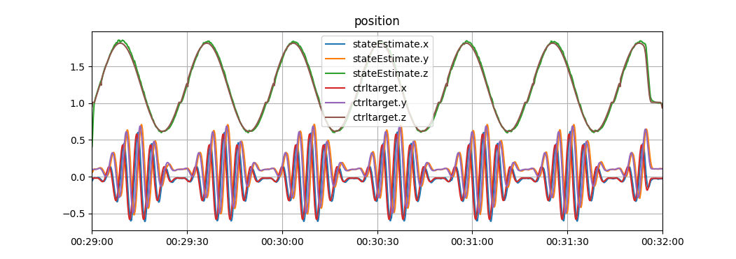
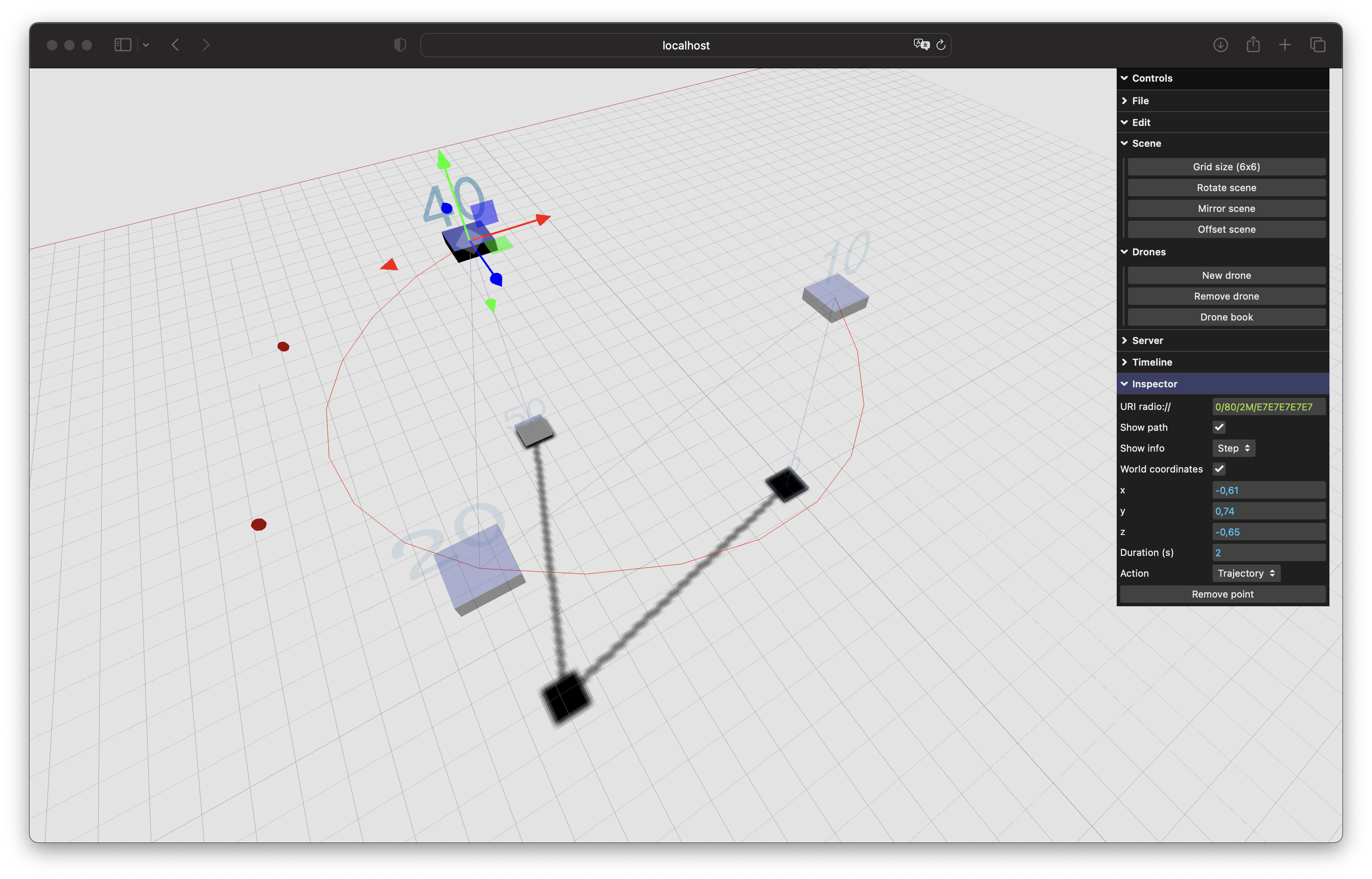
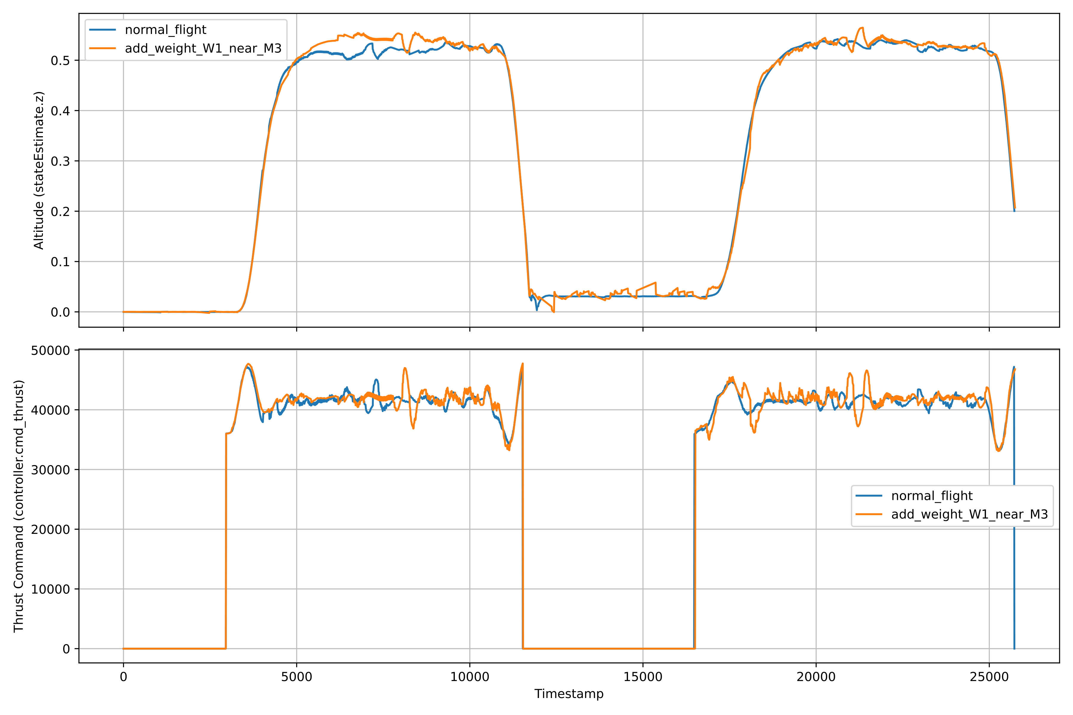
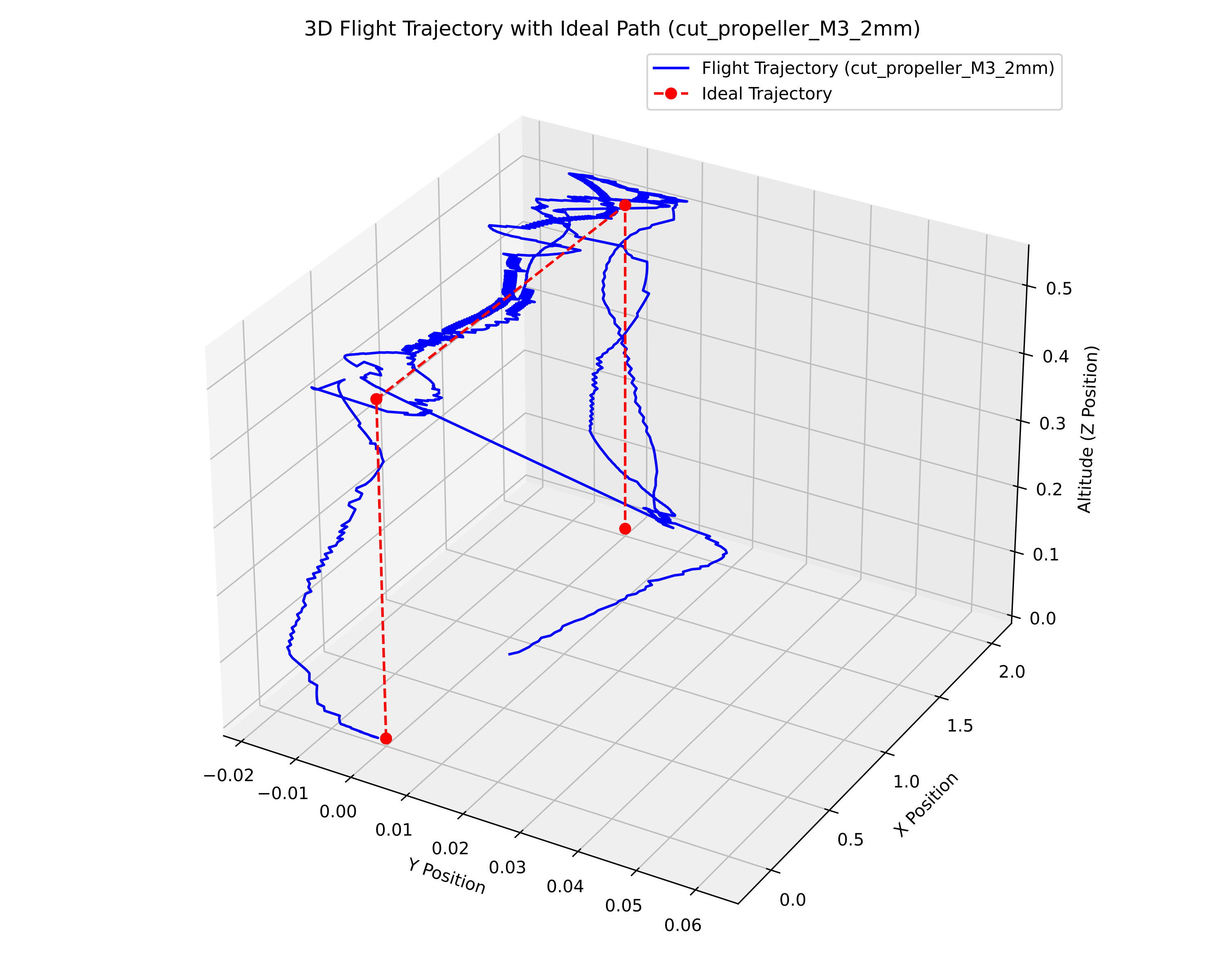
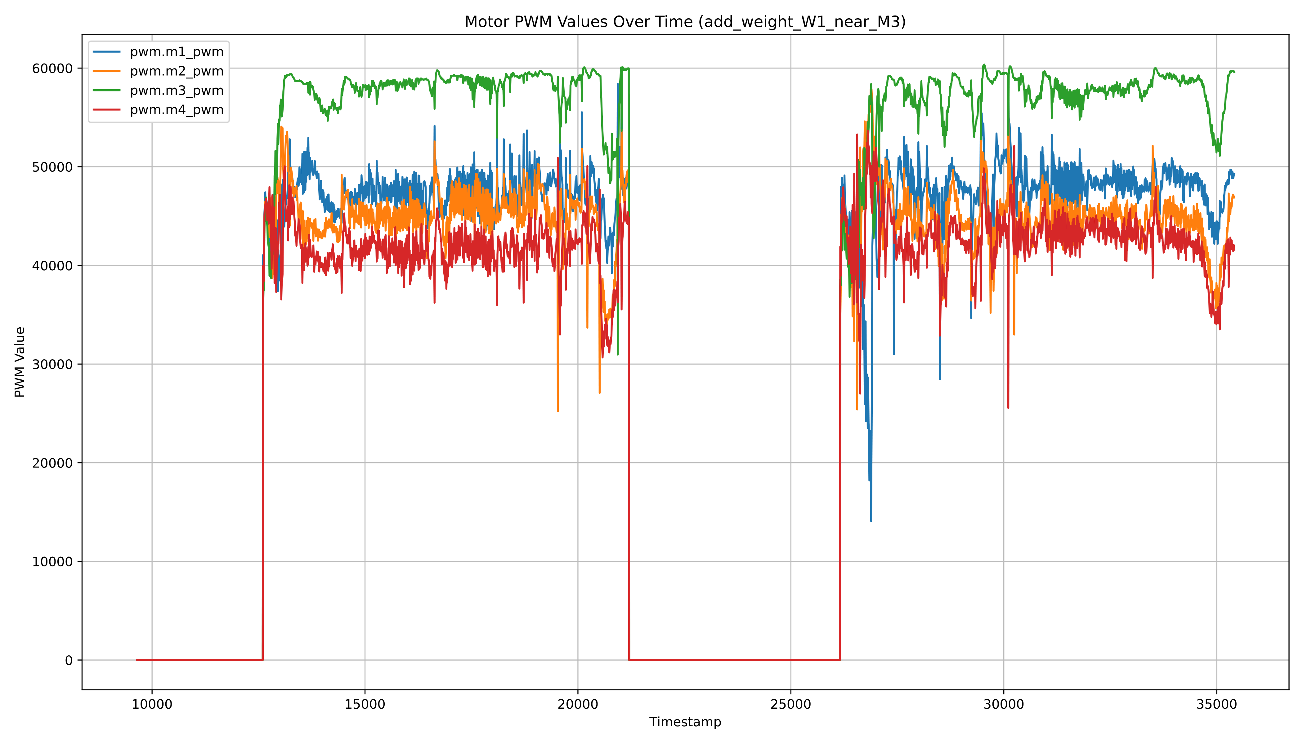
We show Figure 3 as an example of a graph obtained from our dataset. In this figure, you can see the altitude and thrust command over time for different flight conditions. The blue line represents the normal flight, while the orange line represents the flight with additional weight near the M3 propeller. In Figure 4, you can see the 3D flight trajectory of the Crazyflie 2.1 quadcopter under the cut_propeller_M3_2mm condition with the corrected ideal path. The blue line represents the actual flight trajectory, while the red dashed line with markers represents the ideal trajectory. Figure 5 shows the Motor PWM values over time for the add_weight_W1_near_M3 condition. The plot shows the PWM values of each motor (M1, M2, M3, and M4) as they respond to the added weight near the M3 propeller.
More examples of graphs obtained from the CrazyPAD dataset can be found in our research paper specifically describing this dataset: https://doi.org/10.3390/data9060079
Leveraging Research for Diagnostic and Predictive Models
One of the most exciting aspects of our research is its potential application in developing diagnostic and predictive models. The CrazyPAD dataset can be utilized to train machine learning algorithms that detect and predict structural defects in real-time. By analyzing flight data, these models can identify early signs of wear and tear, allowing for proactive maintenance and reducing the risk of in-flight failures.
Diagnostic models can continuously monitor the performance of a UAV, identifying anomalies and pinpointing potential defects. This real-time monitoring can significantly enhance the reliability and safety of UAV operations.
Predictive models can forecast future defects based on historical flight data. By anticipating when and where defects are likely to occur, these models can inform maintenance schedules, ensuring UAVs are serviced before issues become critical.
Why This Matters for the Crazyflie Community
The CrazyPAD dataset and our findings offer valuable resources for the Crazyflie community. By understanding how different defects affect flight performance, developers and enthusiasts can improve design protocols, enhance testing procedures, and ensure higher safety and performance standards for their UAVs.
We believe that sharing our research with the Crazyflie community can lead to significant advancements in UAV technology. The dataset we created is open under the MIT License for further exploration and can serve as a foundation for new innovations and improvements.
Get Involved and Explore Further
We invite community members to explore our full research article and the CrazyPAD dataset. Together, we can drive forward the standards of UAV technology, ensuring that Crazyflie remains at the forefront of innovation and excellence.
Our research paper with a detailed description of this dataset:
Masalimov, K.; Muslimov, T.; Kozlov, E.; Munasypov, R. CrazyPAD: A Dataset for Assessing the Impact of Structural Defects on Nano-Quadcopter Performance. Data 2024, 9, 79. https://doi.org/10.3390/data9060079
Dataset: https://github.com/AerialRoboticsUUST/CrazyPAD
We are eager to collaborate with the Crazyflie community and welcome any feedback or questions regarding our research. Let’s work together to push the boundaries of what’s possible in UAV technology.