It feels like the day of yesterday, when Arnaud, Tobias and Marcus came together in a backyard shed and decided to go fully in developing the Crazyflie 1.0 and start a business. The result that came from that was Bitcraze, and after 10 years we are still here! Also in the course of the next months, we will be releasing more information about the history of Bitcraze on the blog or social media.
But more important we would like you to leave the 19th-21th of October open in your agenda for the grand party, because we will be organizing our own multi day convention: BAM days a.k.a. Bitcraze Awesome Meetup days.
Of-course we did everything we could to come to abbreviation BAM as you can see :)
This event will be fully online and will be filled with (guest) talks, workshops but most importantly: Fika time, which is coffee breaks in Swedish. We really want to put the emphasize on networking and the coffee breaks as we considered the most important part of any conference, seminar or convention. So in between the talks, which will be in a video chat format like Zoom or Google Meet, there will be equally long coffee breaks in spatial chat format as like Gathertown, Mozilla Hubs or MiBo. We are currently browsing to several online event portal alternatives to accommodate all of this to make sure that everything goes smoothly!
We are currently still building up the program and inviting speakers to give talks and workshops. Moreover, we probably will prepare workshops and demos ourselves as well! So please fill in this interest form if you want to receive more information the event, and give us some pointers of the content. Also check out the event page for any current information.
And in the mean time, make sure to keep the 19th to the 21th of October free in your agenda so that you can come and celebrate our 10 year anniversary with us!
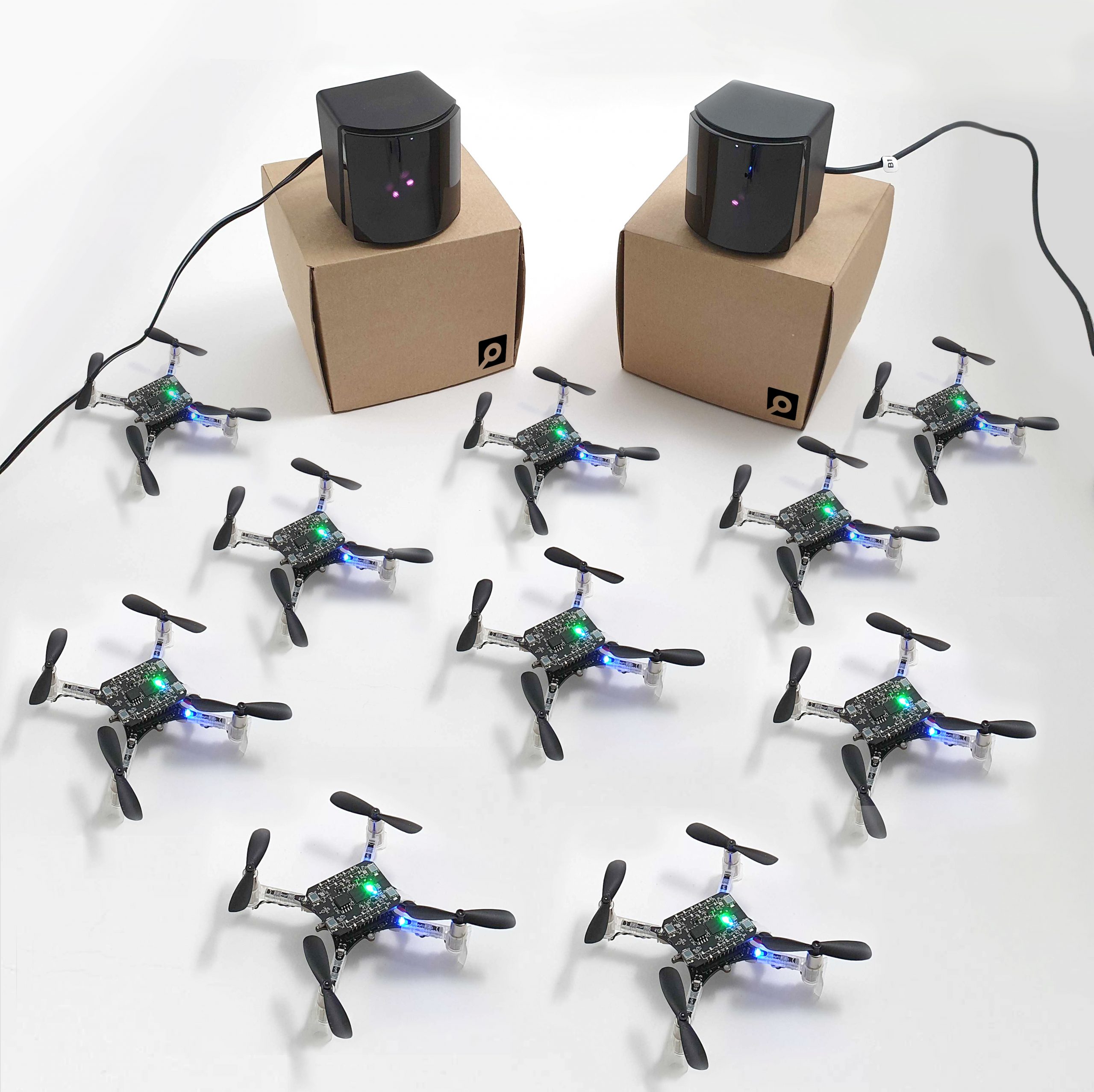
If you haven’t visited our store in a while, you may have missed our new addition: the Lighthouse Swarm bundle!
We’ve been working for some time now on improving the Lighthouse decks and its positioning system. Earlier in the year, we have brought the Lighthouse deck out of early access. While working with it, we have seen the great possibilities and the accuracy of this new positioning system. Thanks to Steam’s VR base station that we use as an optical beacon, the Crazyflie calculates its position with an accuracy better than a decimeter and millimeter precision. It gives a tracking volume of up to 5x5x2 meters with sub-millimetre jitter and below 10 cm accuracy while flying. It’s perfect for a swarm, as it’s accurate, precise and autonomous. We’ve flown our Crazyflies with it a number of time and seen some awesome stuff with it!
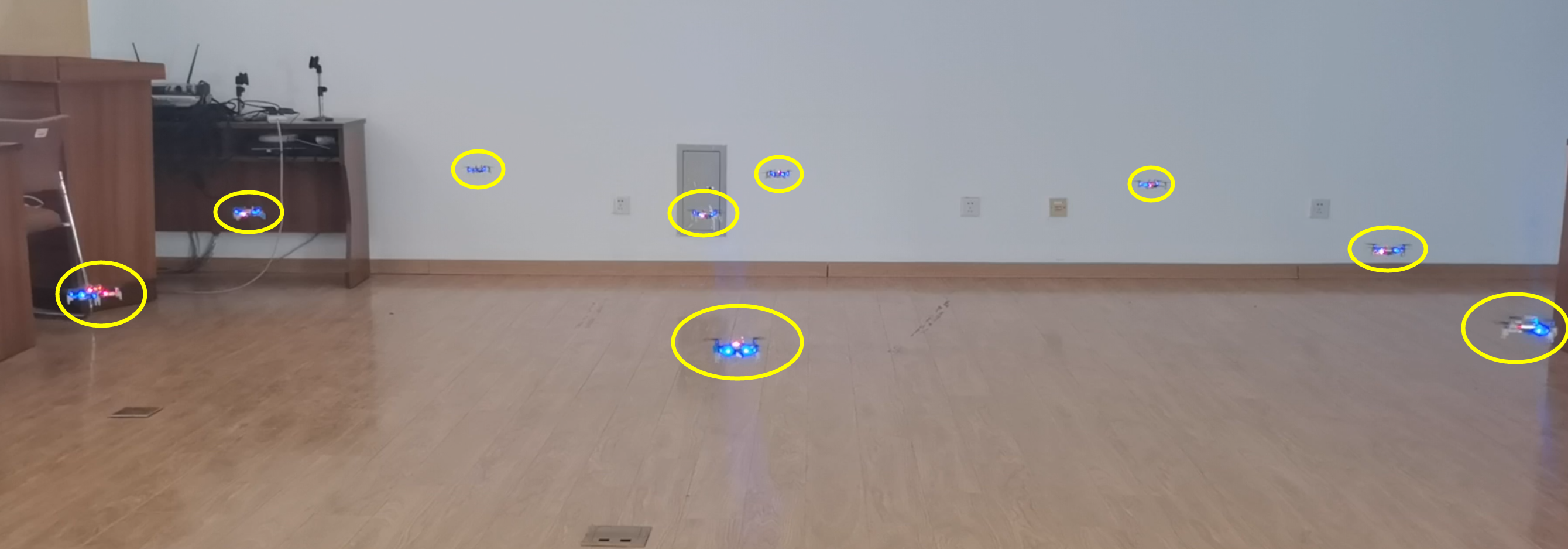
As an example, here is a demo we’ve shown on a conference back in October. We’ve used 8 Crazyflies equipped with Lighthouse decks and Qi chargers, to make a spiraling swarm. A computer orchestrates the Crazyflies and make sure one is flying at all times, while the others re-charge their batteries on their pads. After a pre-programmed trajectory is finished or when the battery of the flying Crazyflie is depleted, it goes back to its pad while another one takes over. The demo had an all-in mode that runs the trajectory on all Crazyflie with sufficient charge at once, the result is quite impressive and demonstrate the great relative precision of the Lighthouse system:
After the launch signal is sent to the Crazyflies, the computer is not required anymore: the Crazyflie will autonomously estimate its position from the lighthouse’s signals. The Crazyflie can estimate its own X, Y and Z in a global coordinate system.
What’s great with the Lighthouse Swarm is that it allows you to do drone research even if you’re on a tighter budget.
And when we got the opportunity to acquire our own base stations (that are also available in the shop by the way), it seemed only logical to offer a Swarm bundle similar to our Loco swarm bundle. So what’s in it ?
While the positioning will work with one base station, two base stations will allow better coverage of the flight space and better stability; as Kimberly can attest, it’s even possible to set it in your kitchen. The Crazyradios allow communication between the Crazyflies and your computer.
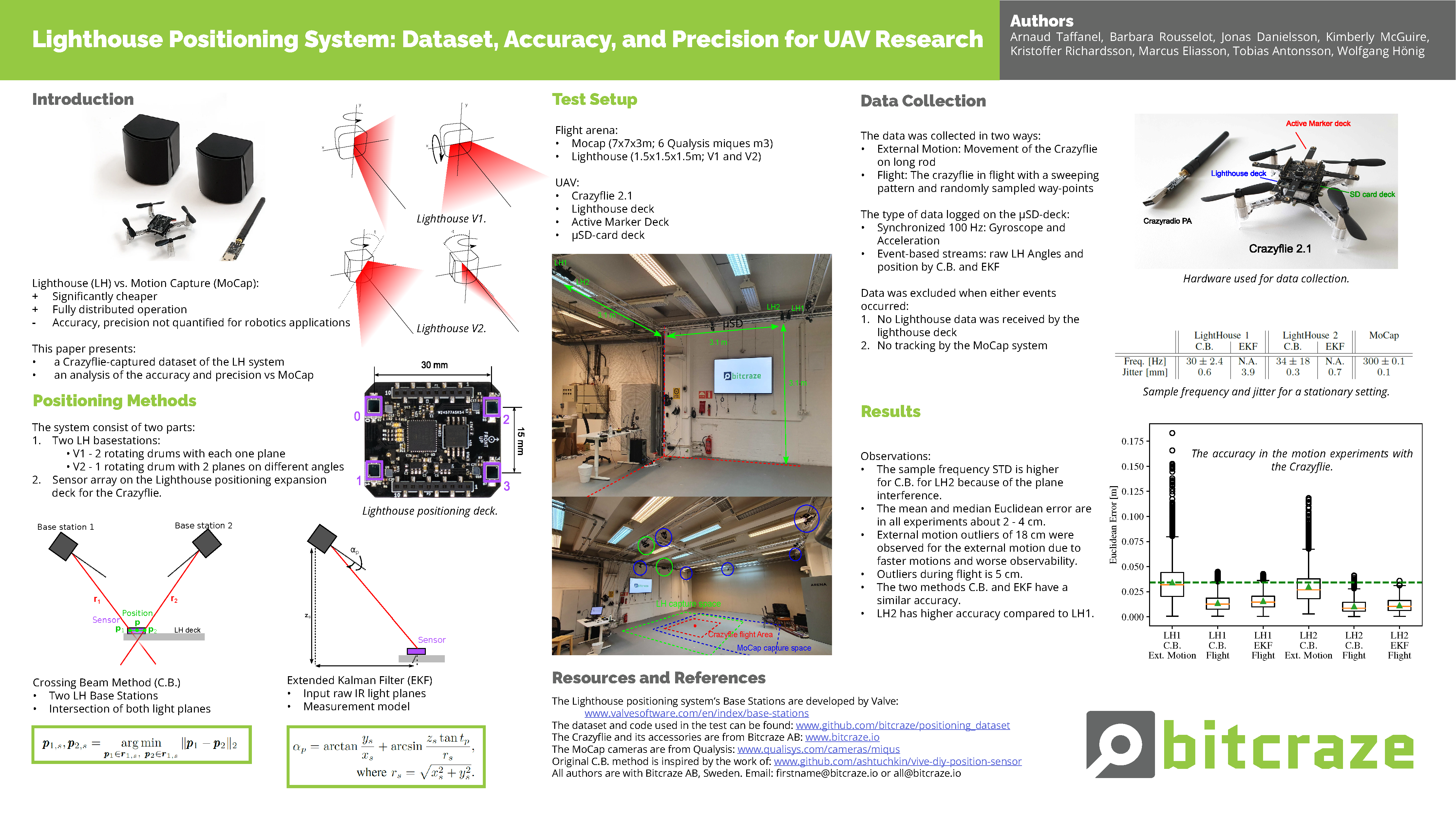
We dedicated a lot of time to the Lighthouse this winter, writing a paper with the help of Wolgangs’ calibration expertise. In this paper, we compared both Lighthouse V1 and V2 with the MoCap system. In all cases, the mean and median Euclidean error of the Lighthouse positioning system are about 2-4 centimeters compared to our MoCap system as ground truth. You can check the paper here, but here is a brief summary we used for our ICRA workshop:
The poster presenting our paper
We are now quite excited to get to see what you will do with this exciting new swarm bundle !
And if you don’t know how to set up the Swarm, you can get started at least with your Lighthouse system in this tutorial or watch Kristoffer explain it in this video:
This week we have a guest blog post from Dr Feng Shan at School of Computer Science and Engineering Southeast University, China. Enjoy!
It is possible to utilize tens and thousands of Crazyflies to form a swarm to complete complicated cooperative tasks, such as searching and mapping. These Crazyflies are in short distance to each other and may move dynamically, so we study the dynamic and dense swarms. The ultra-wideband (UWB) technology is proposed to serve as the fundamental technique for both networking and localization, because UWB is so time sensitive that an accurate distance can be calculated using the transmission and receive timestamps of data packets. We have therefore designed a UWB Swarm Ranging Protocol with key features: simple yet efficient, adaptive and robust, scalable and supportive. It is implemented on Crazyflie 2.1 with onboard UWB wireless transceiver chips DW1000.
Fig.1. Nine Crazyflies are in a compact space ranging the distance with each other.
The Basic Idea
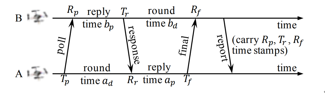
The basic idea of the swarm ranging protocol was inspired by Double Sided-Two Way Ranging (DS-TWR), as shown below.
Fig.2. The exsiting Double Sided-Two Way Ranging (DS-TWR) protocol.
There are four types of message in DS-TWR, i.e., poll, response, final and report message, exchanging between the two sides, A and B. We define their transmission and receive timestamps are Tp, Rp, Tr, Rr, Tf, and Rf, respectively. We define the reply and round time duration for the two sides as follows.
Let tp be the time of flight (ToF), namely radio signal propagation time. ToF can be calculated as Eq. (2).
Then, the distance can be estimated by the ToF.
In our proposed Swarm Ranging Protocol, instead of four types of messages, we use only one type of message, which we call the ranging message.
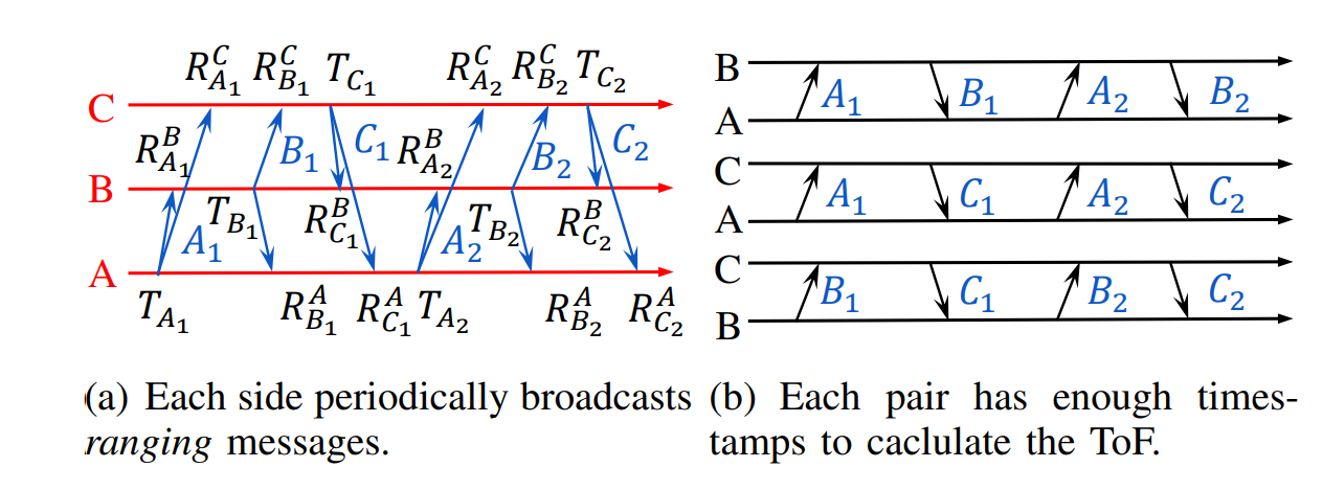
Fig.3. The basic idea of the proposed Swarm Ranging Protocol.
Three sides A, B and C take turns to transmit six messages, namely A1, B1, C1, A2, B2, and C2. Each message can be received by the other two sides because of the broadcast nature of wireless communication. Then every message generates three timestamps, i.e., one transmission and two receive timestamps, as shown in Fig.3(a). We can see that each pair has two rounds of message exchange as shown in Fig.3(b). Hence, there are sufficient timestamps to calculate the ToF for each pair, that means all three pairs can be ranged with each side transmitting only two messages. This observation inspires us to design our ranging protocol.
Protocol Design
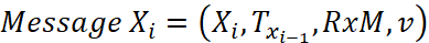
The formal definition of the i-th ranging message that broadcasted by Crazyflie X is as follows.
Xi is the message identification, e.g., sender and sequence number; Txi-1 is the transmission timestamp of Xi-1, i.e., the last sent message; RxM is the set of receive timestamps and their message identification, e.g., RxM = {(A2, RA2), (B2, RB2)}; v is the velocity of X when it generates message Xi.
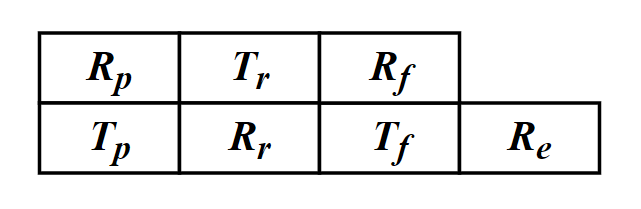
As mentioned above, six timestamps (Tp, Rp, Tr, Rr, Tf, Rf,) are needed to calculate the ToF. Therefore, for each neighbor, an additional data structure is designed to store these timestamps which we named it the ranging table, as shown in Fig.4. Each device maintains one ranging table for each known neighbor to store the timestamps required for ranging.
Fig.4. The ranging table, one for each neighbor.
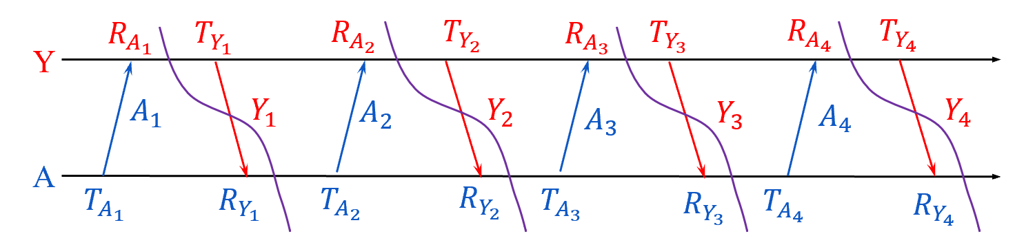
Let’s focus on a simple scenario where there are a number of Crazyflies, A, B, C, etc, in a short distance. Each one of them transmit a message that can be heard by all others, and they broadcast ranging messages at the same pace. As a result, between any two consecutive message transmission, a Crazyflie can hear messages from all others. The message exchange between A and Y is as follows.
Fig.5. Message exchange between A and Y.
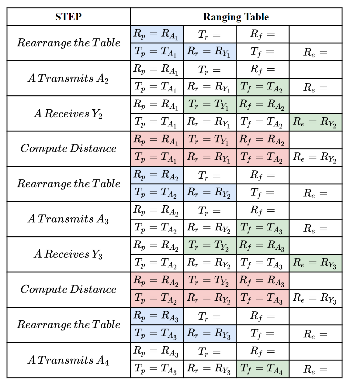
The following steps show how the ranging messages are generated and the ranging tables are updated to correctly compute the distance between A and Y.
Fig.6. How the ranging message and ranging table works to compute distance.
The message exchange between A and Y could be also A and B, A and C, etc, because they are equal, that’s means A could perform the ranging process above with all of it’s neighbors at the same time.
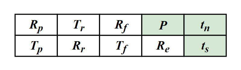
To handle dense and dynamic swarm, we improved the data structure of ranging table.
Fig.7. The improved ranging table for dense and dynamic swarm.
There are three new notations P, tn, ts, denoting the newest ranging period, the next (expected) delivery time and the expiration time, respectively.
For any Crazyflie, we allow it to have different ranging period for different neighbors, instead of setting a constant period for all neighbors. So, not all neighbors’ timestamps are required to be carried in every ranging message, e.g., the receive timestamp to a far apart and motionless neighbor is required less often. tn is used to measure the priority of neighbors. Also, when a neighbor is not heard for a certain duration, we set it as expired and will remove its ranging table.
If you are interested in our protocol, you can find much more details in our paper, that has just been published on IEEE International Conference on Computer Communications (INFOCOM) 2021. Please refer the links at the bottom of this article for our paper.
Implementation
We have implemented our swarm ranging protocol for Crazyflie and it is now open-source. Note that we have also implemented the Optimized Link State Routing (OLSR) protocol, and the ranging messages are one of the OLSR messages type. So the “Timestamp Message” in the source file is the ranging message introduced in this article.
The procedure that handles the ranging messages is triggered by the hardware interruption of DW1000. During such procedure, timestamps in ranging tables are updated accordingly. Once a neighbor’s ranging table is complete, the distance is calculated and then the ranging table is rearranged.
All our codes are stored in the folder crazyflie-firmware/src/deck/drivers/src/swarming.
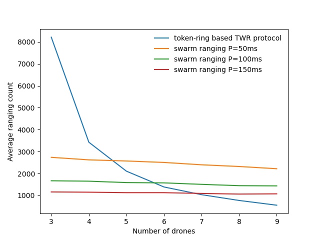
The following figure is a ranging performance comparison between our ranging protocol and token-ring based TWR protocol. It’s clear that our protocol handles the large number of drones smoothly.
Fig.8. performance comparison.
We also conduct a collision avoidance experiment to test the real time ranging accuracy. In this experiment, 8 Crazyflie drones hover at the height 70cm in a compact area less than 3m by 3m. While a ninth Crazyflie drone is manually controlled to fly into this area. Thanks to the swarm ranging protocol, a drone detects the coming drone by ranging distance, and lower its height to avoid collision once the distance is small than a threshold, 30cm.
cd crazyflie-firmware/src/deck/drivers/src/swarming
Then build the firmware.
make clean
make
Flash the cf2.bin.
cfloader flash path/to/cf2.bin stm32-fw
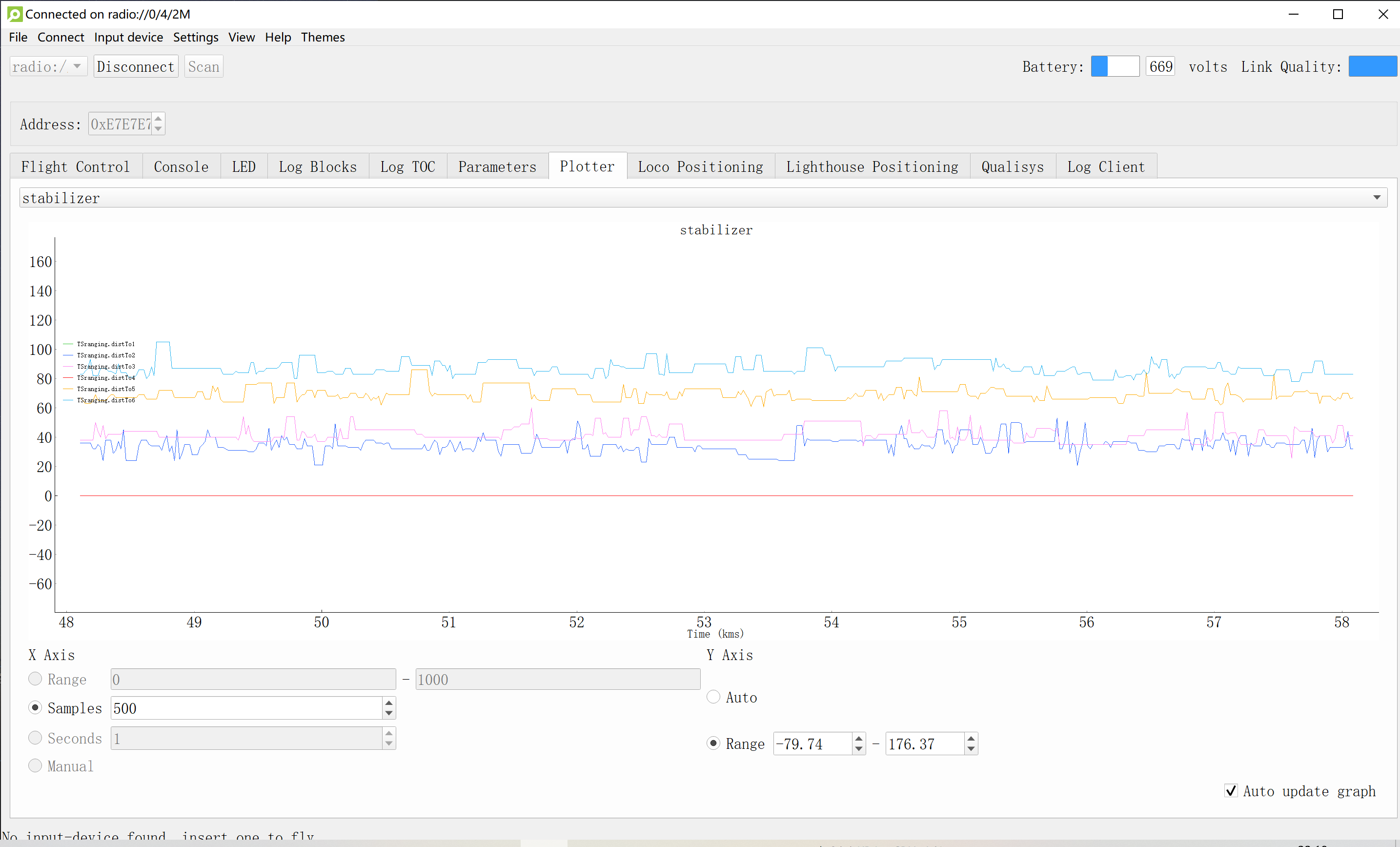
Open the client, connect to one of the drones and add log variables. (We use radio channel as the address of the drone) Our swarm ranging protocol allows the drones to ranging with multiple targets at the same time. The following shows that our swarm ranging protocol works very efficiently.
Summary
We designed a ranging protocol specially for dense and dynamic swarms. Only a single type of message is used in our protocol which is broadcasted periodically. Timestamps are carried by this message so that the distance can be calculated. Also, we implemented our proposed ranging protocol on Crazyflie drones. Experiment shows that our protocol works very efficiently.
For quite a while now, I have been very interested in the Rust programming language and since Jonas joined us we are two rust-enthusiast at Bitcraze. Rust is a relatively recent programming language that aims at being safe, performant and productive. It is a system programming language in the sense that it compiles to machine code with minimal runtime. It prevents a lot of bugs at compile time and it provides great mechanisms for abstraction that makes it sometime feels as high level as languages like Python.
I have been interested in applying my love for Rust at Bitcraze, mostly during fun Fridays. There is two area that I have mainly explored so far: Putting Rust in embedded systems to replace pieces of C, having such a high-level-looking language in embedded is refreshing, and re-writing the Crazyflie lib on PC in rust to make it more performant and more portable. In this blog post I will talk about the later, I keep embedded rust for a future blog post :).
Re-implementing Crazyflie lib
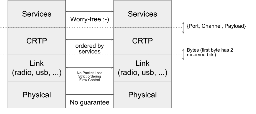
To re-implement the Crazyflie lib, the easiest it to follow the way the communication stack is currently setup, more information can be found on Crtp in a pevious blog post about the Crazyflie radio communication and the communication reliability.
Since I am currently focusing on implementing communication using the Crazyradio dongle, I have separated the implementation in the following modules (A crate is the Rust version of a library):
This organization is very similar to the layering that we have in the python crazyflie-lib, the difference being that in the Crazyflie lib all the layers are distributed in the same Python package.
At the time this blog post is written, the Crazyradio crate is full featured. The link is in a good shape and even has a python binding. The Crazyflie lib however is still very much work in progress. I started by implementing the ‘hard’ parts like log and param but more directly useful part like set-points (what is needed to actually fly the Crazyflie) are not implemented yet.
Compiling to the web: Wasm
One of the nice property of Rust is that compiling to different platform is generally easy and seemless. For instance, all the crates talked about previously will compile and run on Windows/Mac/Linux without any modification including the Python binding using only the standard Rust install. One of the Rust supported platform is a bit more special and interesting compared to the other though: WebAssembly.
WebAssembly is a virtual machine that is designed to be targeted by system programming language like C/C++ and Rust. It can be used in standalone (a bit like the Java VM) as well as in a web browses. All modern web browser supports and can run WebAssembly code. WebAssembly can be called from JavaScript.
The WebAssembly in the web is unfortunately not as easy to target as the native Windows/Mac/Linux: WebAssembly does not support threading yet, USB access needs to be handled via WebUSB and since we run in a web browser from JavaScript we have to follow some rules inherited from it. The most important being that the program can never block (ie. std::sync::Mutex shall not be used, I have tried ….).
I made two major modification to my existing code in order to make it possible to run in a web browser:
crazyflie-link and crazyflie-lib have been re-implemented using Rust async/await. This means that there is no thread needed and Rust async/await interfaces almost seamlessly with Javascript’s promises. The link and lib still compile and work well on native platforms.
I have created a new crate named crazyradio-webusb (not uploaded yet at the release of this post) that exposes the same API as the crazyradio crates but using WebUSB to communicate with the Crazyradio.
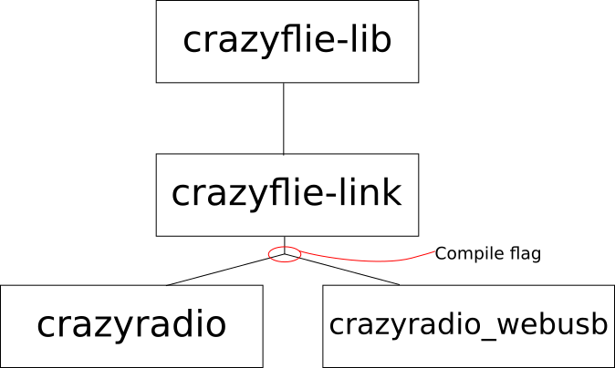
To support the web, the relationship between the crates becomes as follow:
The main goal is to keep the crazyflie-lib and crazyflie-link unmodified. Support for the Crazyradio in native and on the web is handled by two crates that exposes the same async API. The crate used is chosen by a compile flag (called Features in the rust world). This architecture could easily be expanded to other platform like Android or iOS.
Status, demo and future work
I have started getting something working end-to-end in the browser. The lib currently only implements Crazyflie Param and the Log TOC so the current demo scans for Crazyflie, connects the first found Crazyflie and prints the list of parameters with the parameters type and values. It can be found on Crazyflie web client test server. This doesn’t do anything useful now, but I am going to update this server when I make progress, so feel free to visit it in the future :).
Note that WebUSB is currently only implemented by Chromium-based browser so Chrome, Chromium and recent Edge. On Windows you need to install the WinUSB driver for the Crazyradio using Zadig. On Linux/Mac/Android it should work out of the box.
The source code for the Web Client is not pushed on Github yet, once it is, it will be named crazyflie-client-web. It is currently mostly implemented in Rust and it will likely mostly be Rust since it is much easier to stick with one (great!) language. One of the plan is to make a javascript API and to push it on NPM, this will then become a Crazyflie lib usable by anyone on the web from JavaScript (or a bit better, TypeScript …).
My goal for now is to implement a clone of the Crazyflie Client flight control tab on the web. This would provide a nice way to get started with the Crazyflie without having to install anything.
This week we have a guest blog post from Wenda Zhao, Ph.D. candidate at the Dynamic System Lab (with Prof. Angela Schoellig), University of Toronto Institute for Aerospace Studies (UTIAS). Enjoy!
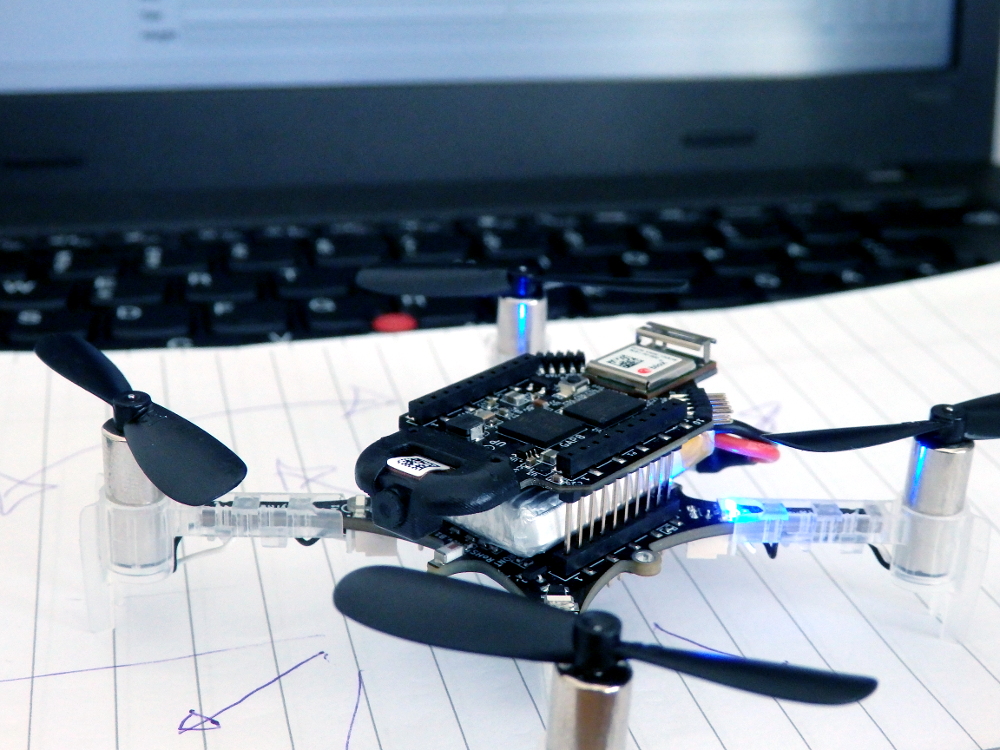
Accurate indoor localization is a crucial enabling capability for indoor robotics. Small and computationally-constrained indoor mobile robots have led researchers to pursue localization methods leveraging low-power and lightweight sensors. Ultra-wideband (UWB) technology, in particular, has been shown to provide sub-meter accurate, high-frequency, obstacle-penetrating ranging measurements that are robust to radio-frequency interference, using tiny integrated circuits. UWB chips have already been included in the latest generations of smartphones (iPhone 12, Samsung Galaxy S21, etc.) with the expectation that they will support faster data transfer and accurate indoor positioning, even in cluttered environments.
A Crazyflie with an IMU and UWB tag flies through a cardboard tunnel. A vision-based motion capture system would not be able to achieve this due to the occlusion.
In our lab, we show that a Crazyflie nano-quadcopter can stably fly through a cardboard tunnel with only an IMU and UWB tag, from Bitcraze’s Loco Positioning System (LPS), for state estimation. However, it is challenging to achieve a reliable localization performance as we show above. Many factors can reduce the accuracy and reliability of UWB localization, for either two-way ranging (TWR) or time-difference-of-arrival (TDOA) measurements. Non-line-of-sight (NLOS) and multi-path radio propagation can lead to erroneous, spurious measurements (so-called outliers). Even line-of-sight (LOS) UWB measurements exhibit error patterns (i.e., bias), which are typically caused by the UWB antenna’s radiation characteristics. In our recent work, we present an M-estimation-based robust Kalman filter to reduce the influence of outliers and achieve robust UWB localization. We contributed an implementation of the robust Kalman filter for both TWR and TDOA (PR #707 and #745) to Bitcraze’s crazyflie-firmware open-source project.
Methodology
The conventional Kalman filter, a primary sensor fusion mechanism, is sensitive to measurement outliers due to its minimum mean-square-error (MMSE) criterion. To achieve robust estimation, it is critical to properly handle measurement outliers. We implement a robust M-estimation method to address this problem. Instead of using a least-squares, maximum-likelihood cost function, we use a robust cost function to downweigh the influence of outlier measurements [1]. Compared to Random Sample Consensus (RANSAC) approaches, our method can handle sparse UWB measurements, which are often a challenge for RANSAC.
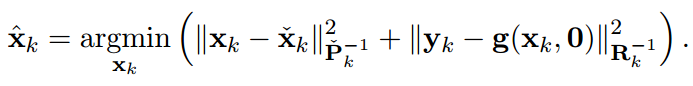
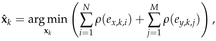
From the Bayesian maximum-a-posteriori perspective, the Kalman filter state estimation framework can be derived by solving the following minimization problem:
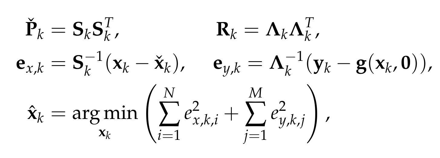
Therein, xk and yk are the system state and measurements at timestep k. Pk and Rk denote the prior covariance and measurement covariance, respectively. The prior and posteriori estimates are denoted as xk check and xk hat and the measurement function without noise is indicated as g(xk,0). Through Cholesky factorization of Pk and Rk, the original optimization problem is equivalent to
where ex,k,i and ey,k,j are the elements of ex,k and ey,k. To reduce the influence of outliers, we incorporate a robust cost function into the Kalman filter framework as follows:
where rho() could be any robust function (G-M, SC-DCS, Huber, Cauchy, etc.[2]).
By introducing a weight function for the process and measurement uncertainties—with e as input—we can translate the optimization problem into an Iteratively Reweighted Least Squares (IRLS) problem. Then, the optimal posteriori estimate can be computed through iteratively solving the least-squares problem using the robust weights computed from the previous solution. In our implementation, we use the G-M robust cost function and the maximum iteration is set to be two for computational reasons. For further details about the robust Kalman filter, readers are referred to our ICRA/RA-L paper and the onboard firmware (mm_tdoa_robust.c and mm_distance_robust.c).
Performance
We demonstrate the effectiveness of the robust Kalman filter on-board a Crazyflie 2.1. The Crazyflie is equipped with an IMU and an LPS UWB tag (in TDOA2 mode). With the conventional onboard extended Kalman filter, the drone is affected by measurement outliers and jumps around significantly while trying to hover. In contrast, with the robust Kalman filter, the drone shows a more reliable localization performance.
Conventional extended Kalman filter
M-estimation-based robust Kalman filter
Quadcopter is commanded to hover. UWB TDOA-based localization performance of standard method on-board a Crazyflie 2.1 quadcopter (left) and the proposed robust Kalman filter (right).
The robust Kalman filter implementations for UWB TWR and TDOA localization have been included in the crazyflie-firmware master branch as of March 2021 (2021.03 release). This functionality can be turned on by setting a parameter (robustTwr or robustTdoa) in estimator_kalman.c. We encourage LPS users to check out this new functionality.
As we mentioned above, off-the-shelf, low-cost UWB modules also exhibit distinctive and reproducible bias patterns. In our recent work, we devised experiments using the LPS UWB modules and showed that the systematic biases have a strong relationship with the pose of the tag and the anchors as they result from the UWB radio doughnut-shaped antenna pattern. A pre-trained neural network is used to approximate the systematic biases. By combining bias compensation with the robust Kalman filter, we obtain a lightweight, learning-enhanced localization framework that achieves accurate and reliable UWB indoor positioning. We show that our approach runs in real-time and in closed-loop on-board a Crazyflie nano-quadcopter yielding enhanced localization performance for autonomous trajectory tracking. The dataset for the systematic biases in UWB TDOA measurements is available on our Open-source Code & Dataset webpage. We are also currently working on a more comprehensive dataset with IMU, UWB, and optical flow measurements and again based on the Crazyflie platform. So stay tuned!
Reference
[1] L. Chang, K. Li, and B. Hu, “Huber’s M-estimation-based process uncertainty robust filter for integrated INS/GPS,” IEEE Sensors Journal, 2015, vol. 15, no. 6, pp. 3367–3374.
[2] K. MacTavish and T. D. Barfoot, “At all costs: A comparison of robust cost functions for camera correspondence outliers,” in IEEE Conference on Computer and Robot Vision (CRV). 2015, pp. 62–69.
Feel free to contact us if you have any questions or suggestions: wenda.zhao@robotics.utias.utoronto.ca.
Please cite this as:
<code>@ARTICLE{Zhao2021Learningbased,
author={W. {Zhao} and J. {Panerati} and A. P. {Schoellig}},
title={Learning-based Bias Correction for Time Difference of Arrival Ultra-wideband Localization of Resource-constrained Mobile Robots},
journal={IEEE Robotics and Automation Letters},
volume={6},
number={2},
pages={3639-3646},
year={2021},
publisher={IEEE}
doi={10.1109/LRA.2021.3064199}}
</code>
In the past couple of weeks we have been busy trying to improve the development interface of the Crazyflie. We want to make developing with and for the platform a more pleasant experience.
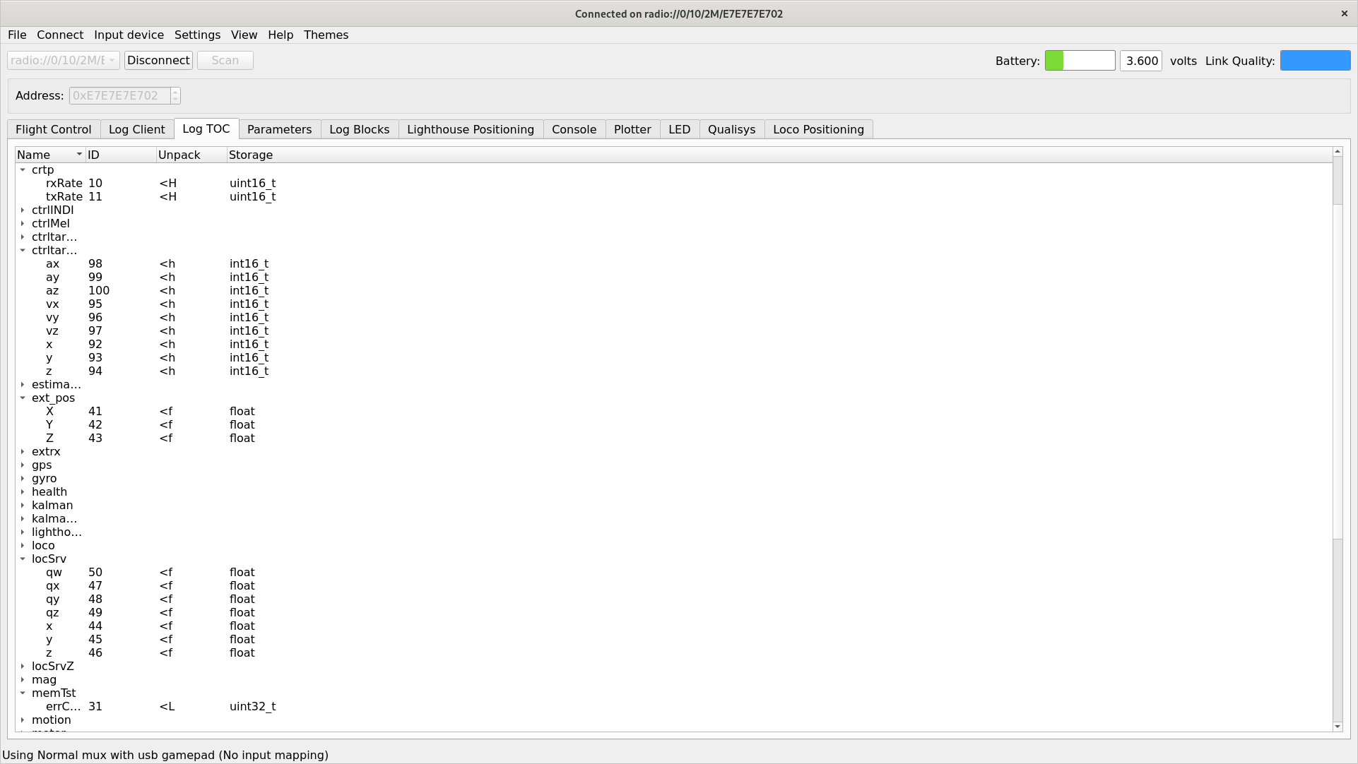
We have started looking at the logging- and parameter framework and how to improve it for our users. The aim of this framework is to easily be able to log data from the Crazyflie and to set variables during runtime. Your application can use them to control the behavior of the platform or to receive data about what it is currently up to. As of today, in the firmware there are 227 parameters and 467 logging variables defined.
View from the cfclient of the different logging variables one could subscribe to
These logging variables and parameters have been added to the Crazyflie firmware over the course of years. Some are critical infrastructure, needed to be able to write proper applications that interface with the platform. Some are duplicates or were added as debug years ago. Others have in some way outlived their usefulness as the firmware and functionality has moved on. The problem is that we have no way of conveying this information to our users and this is what we are trying to rectify.
An attempt of stability
We are currently reviewing all of our logging variables and parameters in an attempt to make the situation clearer for our users … and ourselves. We are adding documentation to make the purpose of each individual parameters and logging variables more clear. And we are also dividing them up into two categories: core and non-core.
If a parameter or logging variable is marked as core in the firmware that constitutes a promise that we will try very hard to not remove, rename or in any other way change the behavior of it. The idea is that this variable or parameter can be used in applications without any fear or doubt about it going away.
If a variable or parameter is non-core it does not mean that it is marked for removal. But, it could mean that we need more time to make sure that it is the proper interface for the platform. It means that it could change in some way or in some cases be removed in later firmware releases.
The reason for doing this is twofold: we want to make the Crazyflie interface clearer for our users and we want something that we feel we can maintain and keep an up-to-date documentation of.
What is the result?
We have introduced a pair of new macros to the firmware, LOG_ADD_CORE and PARAM_ADD_CORE which can be used to mark a parameter or variable as core. When using these we also mandate that there should be a Doxygen comment attached to the macro.
Below is an example from the barometer log group, showing the style of documentation expected and how to mark a logging variable as core. Parameters gets treated in the same way.
/**
 * Log group for the barometer
 */
LOG_GROUP_START(baro)

/**
 * @brief Altitude above Sea Level [m]
 */
LOG_ADD_CORE(LOG_FLOAT, asl, &sensorData.baro.asl)

/**
 * @brief Temperature [degrees Celsius]
 */
LOG_ADD(LOG_FLOAT, temp, &sensorData.baro.temperature)

/**
 * @brief Air pressure [mbar]
 */
LOG_ADD_CORE(LOG_FLOAT, pressure, &sensorData.baro.pressure)

LOG_GROUP_STOP(baro)
We have also added a script In the firmware repository: elf_sanity.py. The script will return data about parameters and logging variables that it is included in a firmware elf. This can be used to count the number of core parameters. If we point it to a newly built Crazyflie elf, after we’ve done our initial review pass of the parameters and variables, we get the result below.
$ python3 tools/build/elf_sanity.py --core cf2.elf
101 parameters and 78 log vars in elf
To produce a list of the parameters and variables you can add the --list-params and --list-logs options to the script.
What is the next step?
Once we have finished our review of the parameters and logging variables we will explore different ways of making the documentation of them available in a clear and accessible way. And we will come up with a scheme for making changes to the set of parameters and variables. Once this is all finished you can expect an update from us.
The end goal of our efforts is making developing for the Crazyflie a smoother process, and we would love to hear from you. What is confusing? What are your pain points? Let us know! So we can do better.
As you have noticed, we talk about the lighthouse positioning a lot these last couple of months ever since we got it out of early release. However, it is good to realize that it is not the only option out there for positioning your Crazyflie! That is why in this blog-post we will lay out possible options and explain how they are different/similar to one another.
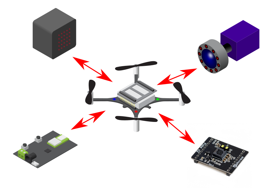
The four possible ways to position the crazyflie
Absolute Positioning / Off-board Pose Estimation
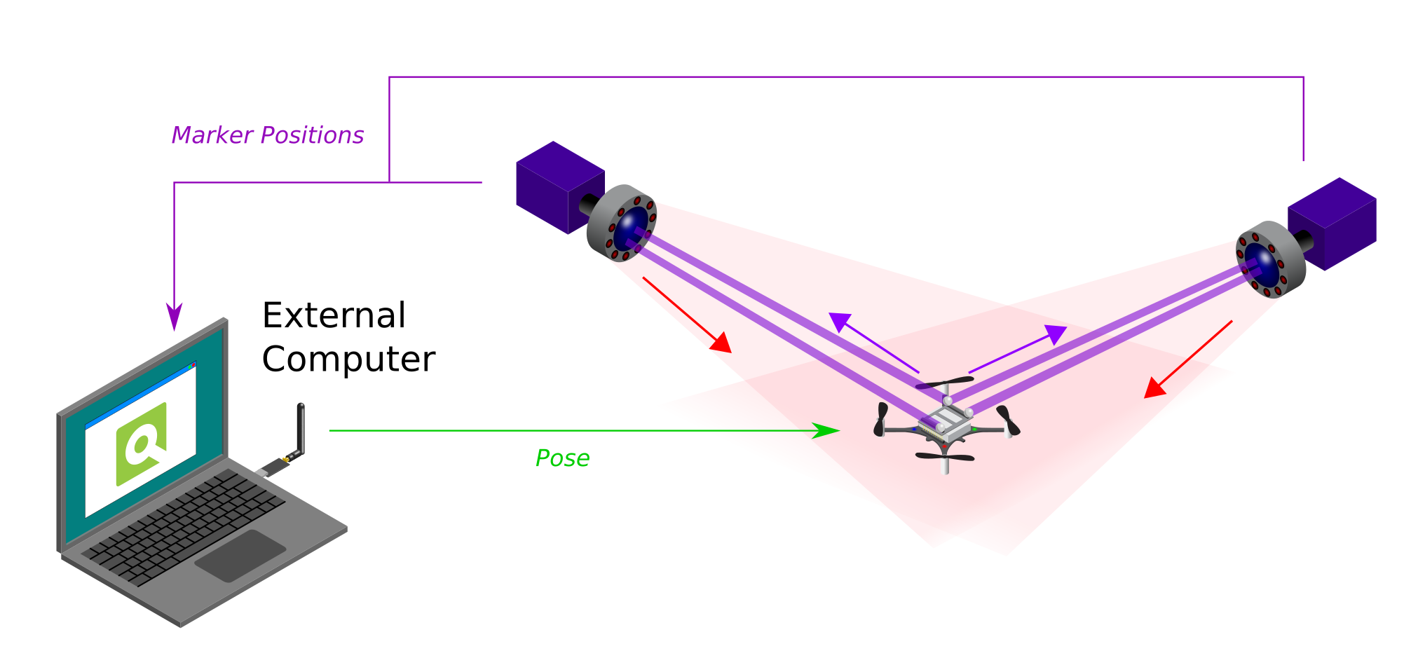
Absolute Positioning and External Pose Estimation with the MoCap System
The first we will handle are the use of motion capture systems (MoCap), which resolves around the use of InfraRed cameras and Markers. We use the Qualysis camera ourselves but there are also labs out there that use Vicon or Optitrack. The general idea is that the cameras have an IR-light-emitting LED ring, which are bounced back by reflective markers that are supposed to be on the Crazyflie. These markers can therefore be detected by the same cameras, which pass through the marker positions to an external computer. This computer will have a MoCap program running which will turn these detected markers into a Pose estimate, which will in turn be communicated to the Crazyflie by a Crazyradio PA.
Since that the positioning is estimated by an external computer instead of onboard of the crazyflie, a MoCap positioning system is categorized as an off-board pose estimation using an absolute positioning system. For more information, please check the Motion Capture positioning documentation.
Absolute Positioning / On-board Pose Estimation
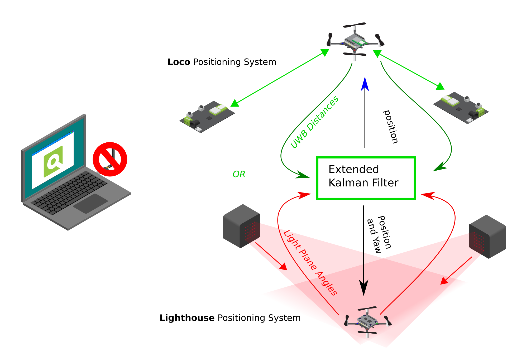
Absolute Positioning and Internal Pose Estimation with the Lighthouse and Loco Positioning System
The next category is a bit different and it consists of both the Loco positioning system and the Lighthouse positioning system. Even though these both use beacons/sensors that are placed externally of the Crazyflie, the pose estimation is done all on-board in the firmware of the Crazyflie. So there is no computer that is necessary to communicate the position back to the Crazyflie. Remember that you do need to communicate the reference set-points or high level commands if you are not using the App layer.
Of course there are clear differences in the measurement type. A Crazyflie with the Locodeck attached takes the distance to the externally placed nodes as measured by ultra wide band (UWB) and the Lighthouse deck detects the light plane angles emitted by the Lighthouse Base Stations. However the principle is the same that those raw measurements are used as input to the Extended Kalman filter onboard of the Crazyflie, and outputs the estimated pose after fusing with the IMU measurements.
Therefore these systems can be classified as absolute positioning systems with on-board pose estimation. To learn more please read the Loco and Lighthouse positioning system documentation!
Relative Positioning / On-board Pose Estimation
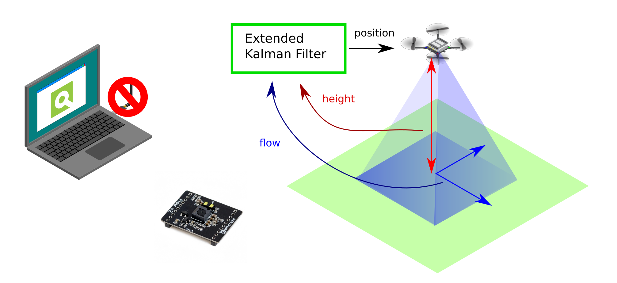
Relative Positioning and Internal Pose Estimation with the Flowdeck V2.
It is not necessary to have to setup an external positioning system in your room in order to achieve a form of positioning on the Crazyflie. With the Flowdeck attached, the Crazyflie can measure flows per frame with an optical flow sensor and the height in millimetres with a time of flight sensor. These measurements are then fused together with the IMU within the Extended Kalman filter (see the Flow deck measurement model), which results in a on-board pose estimation.
The most important difference here to note is that positioning estimated by only the Flowdeck, will not result in a absolute positioning estimate but a relative one. Instead of using an external placed system (like MoCap, Lighthouse and Loco) which dictate where the zero position is in XYZ, the start-up position the Crazyflie determines where the origin of the coordinate system is. That is why the Flowdeck is classified as a Relative Positioning System with On-board Pose Estimation.
IMU-only On-board Pose Estimation ?
Oh boy… that is a different story. Theoretically it could be possible by using the onboard accelerometers of the crazyflie and fusing those in some short of estimator, however practice has shown that the Crazyflie’s accelerometers are too noisy to result in any good pose estimation… We haven’t seen any work that has been successfully to achieve any stable hover on only the IMU of the Crazyflie, but if you have done/see research that has, please let us know!
And if you would like to give a go yourself and build an estimator that is able to do this, please check out the new out of tree build functionality for estimators. This is still work in progress so it might have some bugs, but it should enable you to plugin in your own estimator separate from the Crazyflie firmware ;)
Documentation
We try to keep keep all the information of all our positioning systems on our website. So check out the positioning system overview page to be referred to more details if you would be interested in a particular system that fits your requirements!
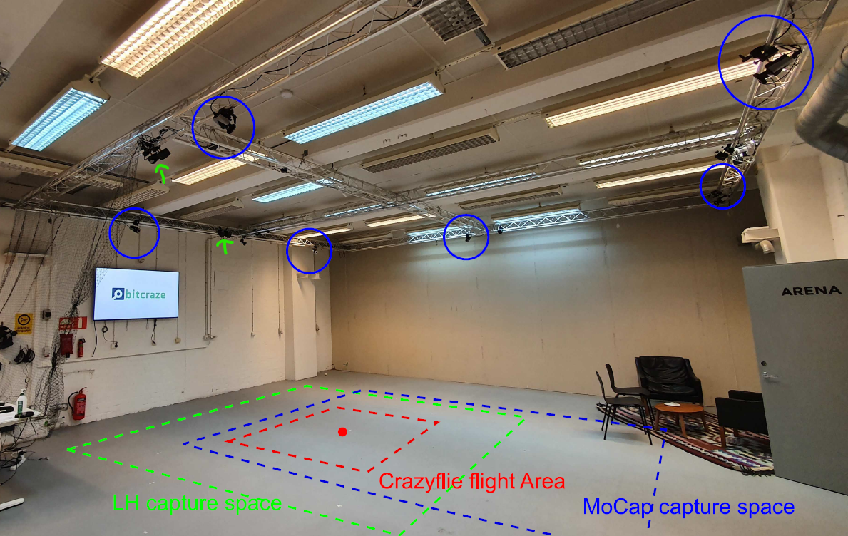
During Wolfgang Hönig‘s time here at Bitcraze, one of the bigger projects we worked together on was to generate a dataset comparing the positioning quality of the Lighthouse system with a Motion Capture (MoCap) system. You could imagine that would be a difficult task, since as the lighthouse basestations transmit infrared light sweeps and MoCap cameras by default also emit IR light which are reflected back by markers. However, with the Active marker deck for the Qualysis system, we were able to use the MoCap and Lighthouse positioning without too much interference.
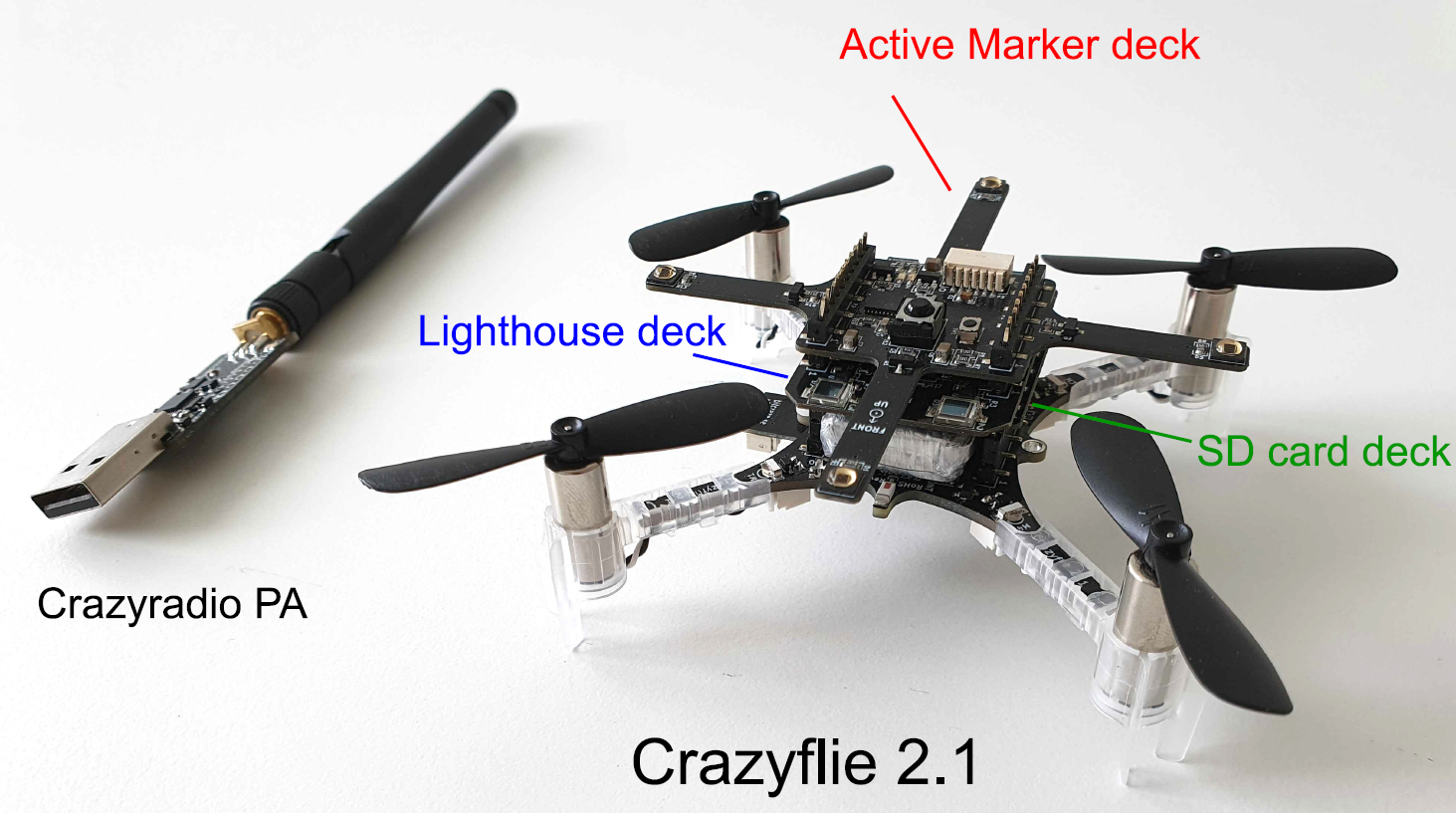
Moreover, Wolfgang also helped out with improving the logging quality on the Micro-SD-card deck which also enabled us to get as much data real-time as possible. He wrote a blogpost about event-based logging a few weeks ago which is a new approach to record data on the Crazyflie at a fast pace. With the Active Marker Deck, the Micro-SD-card deck and of course the Lighthouse deck, … the Crazyflie turn into a full-blown positioning data-collection machine!
The configuration of the Crazyflie with the Micro-SD-card deck, the Lighthouse-deck from the lighthouse dataset paper
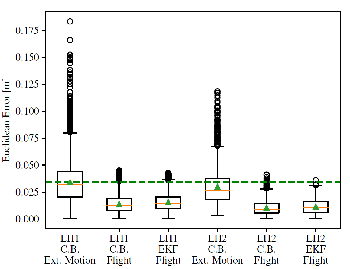
This paper contains an short explanation of the lighthouse system, how we set up the data collection and an analysis of the results, where we compared both Lighthouse V1 and V2 with the Crossing beam (C.B.) method and the extended Kalman filter. In all cases, the mean and median Euclidean error of the Lighthouse positioning system are about 2-4 centimeters compared to our MoCap system as ground truth.
The Euclidean Error of both LH1 and LH2 with Mocap as ground-truth taken from the dataset paper.
ICRA Swarm Workshop
Our paper is selected for a poster presentation at the ICRA 2021 Workshop: Robot Swarms in the Real World. So if you have any questions about the paper, please join and ask us in person! The workshop will be held on the 4th of June.
Moreover, we also are sponsoring the event by giving away a Lighthouse Swarm Bundle to whomever wins the best video-demonstration award! So to all the participants, the best of luck! We are super curious to what you’ll have to show us.
A little while ago we made a blog post talking about the communication reliability, one part of this work did include an alternative CRTP link implementation for the Crazyflie lib. This week we will make one of the native CRTP link implementations, the Crazyflie-link-Cpp, the default link for the Crazyflie python lib.
In the Crazyflie communication stack, the CRTP link is the piece of software that handles reliable packet communication between a computer and the Crazyflie. In the Crazyflie it is mainly implemented in the nRF51 radio chip (for the radio link), in the computer it is part of the Crazyflie python lib + Crazyflie client and for Ros and Crazyswarm it is implemented in crazyflie-cpp. Other clients like Lamouchefolle also have re-implemented their own versions of the CRTP link.
The CRTP link is the most critical part in the communication with Crazyflie, if it is not working properly, nothing can work properly, all communication with the Crazyflie passes though the CRTP link. This code duplication in multiple projects means that we have many places for diverging behaviour and creative bugs which makes it hard to develop new clients for the Crazyflie.
One way we are trying to solve this problem is to unify the links: let’s try to use the same link in all the clients. In order to do so we need a link that can act as a minimum common denominator: it needs to work with Python in order to accommodate the Crazyflie Python lib, work with C++ for Crazyswarm and LaMoucheFolle and be high-performance to be able to handle swarms of Crazyflies. The C++ link implementation can full-fill all these requirements using a python binding, and it will give higher performance to the Python lib.
Switching to the native C++ link will give us a lot of benefits:
It is higher performance, it has about 20% higher packet throughput than the pure python implementation
It will unify the Python lib and Crazyswarm a bit more. Crazyswarm will be able to use the same link as soon as broadcast packet support is added.
The Cpp link supports dynamic allocation of radios, no need to choose what radio to use for each connection, the link will distribute connections over all available radios by using a star instead of the radio number (radio://*/80/2M) in the URI.
The biggest drawback so far is that the CPP link needs to be compiled for each platform. We are compiling a python Wheel for it in Github actions for Windows/Mac/Linux on X86_64, any other architecture (including raspberry pi) will use the existing python CRTP link for the time being.
We are in the process of enabling the new link as the default in the lib. There are still some outstanding bugs related to boot loading that needs to be ironed out, but we expect this change to be included in the next release.
The AI-deck consists of the GAP8 chip developed by Greenwaves Technologies. On their website there’s an explanation of development tools where you get a general understanding of what you can use. Also their GAP SDK documentation explains how to install and try out some of their examples as well, on both a GAP8 simulator on the computer or on the GAP8 chip on the AI-deck itself.
Recently we also added the AIdeck documentation to the Bitcraze website, generated from the docuemtnation already available in the Github repository. There’s still improvements to make, so if you find any issues or any additions needed, don’t hesitate to help us improve it. On the bottom there is an ‘improve this page’ link where you can give the suggested change, or notify us by posting on the issue list of the AIdeck repository.
Also note that we have a separate AI-deck category on our forum where you can search for or add any AI-deck related questions. Remember that posting the issues that you are having will also help us to improve the platform and hopefully soon get it out of Early Access.
Workshop by PULP-platform
On the 16th of April we hosted a workshop given by PULP-platform featuring Greenwaves Technologies. In the workshop the an overview of the AI-deck and GAP8 was given as well as going through some basic hands-on exercises. About 70 people joined the workshop and we were happy it was so well received.
The workshop is a great source of information for anybody who is just getting started with the AI-deck, so have a look at the recordings on Youtube and the slides on the event page. Also make sure to check out their PULP training page for more tools that also can be used on the AI-deck. A big thanks to the PULP-platform and Greenwaves Technologies for taking part in the workshop!
Also we would like to ask if anybody who joined the workshop, to fill in this small questionnaire so that we can get some more feedback on how it went and how we can improve for the next one.