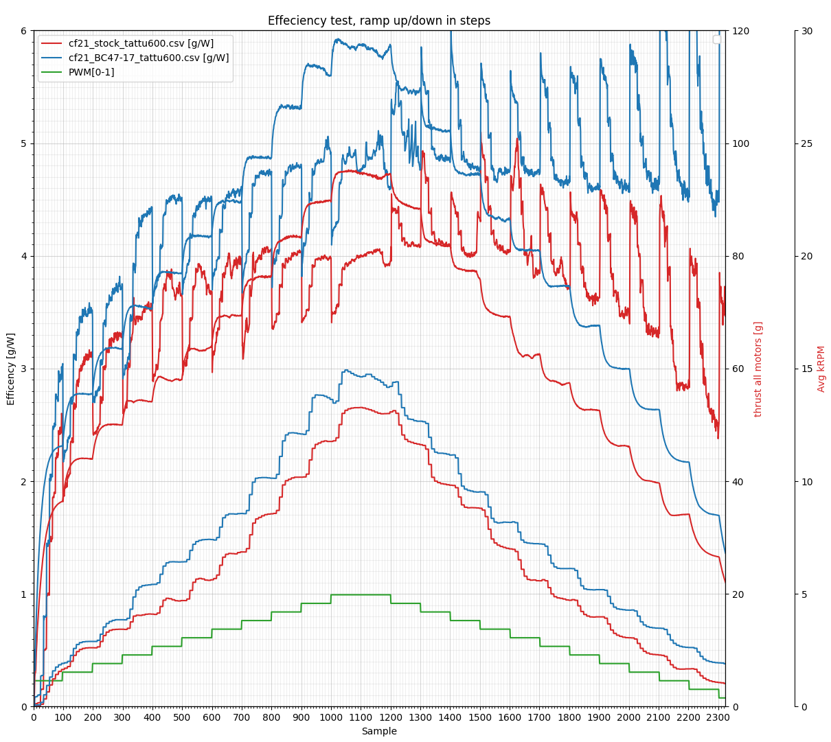
Last week our brand new 47-17 (47mm diameter, 17mm pitch) Crazyflie 2.X propeller became available in black and green in the shop! It is a custom designed propeller for the 0.8mm shaft, 7×16 coreless brushed motor, that comes with the Crazyflie 2.X. The improved design boosts the efficiency, both flight time and maximum thrust is increased with up to 15%. It is made in polycarbonate (PC) which makes it more durable so that it will withstand crashes better. The new propeller is better then the stock 45-17 in almost all areas except in noise where the new 47-17 propeller runs at a higher RPM. Below is a graph comparing the two propellers using the thrust stand we previously built. The graph is a bit messy but hopefully you can figure it out! The big takeaway is that the 45-35 propeller tops at ~4 g/W while the 47-17 tops at ~4.7 g/W using the stock 7×16 motor.
The Crazyflie 2.1 kit will continue to be shipped with the “stock” 45-35 propeller. At some point we want to switch to the new propeller in the kit. We don’t know when this will happen yet and will of course announce it here at that point :-).
After a nice (but rainy) summer, everyone is back at the office and we’re coming back to business as usual at Bitcraze. This blog post is dedicated to various bits of news, in order to get you caught up on what’s been happening during the summer.
Dev meeting theme
There were no dev meetings in August to allow everyone to rest and enjoy their vacations, but after this hiatus, we’re back in the saddle! The dev meeting will happen, as usual, on the first Wednesday of the month, so the 6th of September, at 15.00 CEST.
This month, Arnaud is going to talk about the lib: what is its current status, its architecture, and some hopes we have for the future. As usual, we’ll have a short presentation, and then a discussion; you can also join if you have more general questions or feedback. If you’re interested and willing to take part in this discussion, you can check the information on Github: https://github.com/orgs/bitcraze/discussions/884
Chargers out of stock
Some items were out of stock during the summer (like the HQ propellers) that we thankfully received soon after we came back. Unfortunately, one product is still not available: the battery charger. Since it’s part of the Swarm bundles, it also means that the bundles are out of stock too. But the wait for their restocking shouldn’t be too long, as they are scheduled to arrive around the end of next week. We’re hoping it’s not a big inconvenience for you and we thank you for your patience!
Problems with payment
We’ve noticed that some of you had some problems getting their payment through in our shop. If you’re one of the unlucky ones who faced this issue, we apologize for the inconvenience, and we want you to know we’re working with our payment provider to figure out a solution. This, unfortunately, can take some time because of the number of parties involved (there’s us, the payment provider, different banks, so the situation gets quite complex quickly). In the meantime, if you should encounter such a problem, don’t hesitate to send us an email at contact@bitcraze.se and we can help out. It would also help us to know who is facing this issue.
Today, Vivek Adajania from Learning Systems and Robotics lab write about a project for a safe motion planning of Crazyflie swarm that was published at ICRA 2023. Enjoy!
Motivation
Quadrotor swarms offer significant potential in applications like search and rescue, environmental mapping, and payload transport due to their flexibility and robustness compared to single quadrotors. The core challenge in these applications is collision-free and kinematically feasible trajectory planning. As the quadrotors share space, they must safely manoeuvre around each other and avoid collisions with static obstacles. Existing solutions [1] [2], while effective for generating collision-free trajectories, often struggle in densely cluttered scenarios due to simplifying approximations.
Background
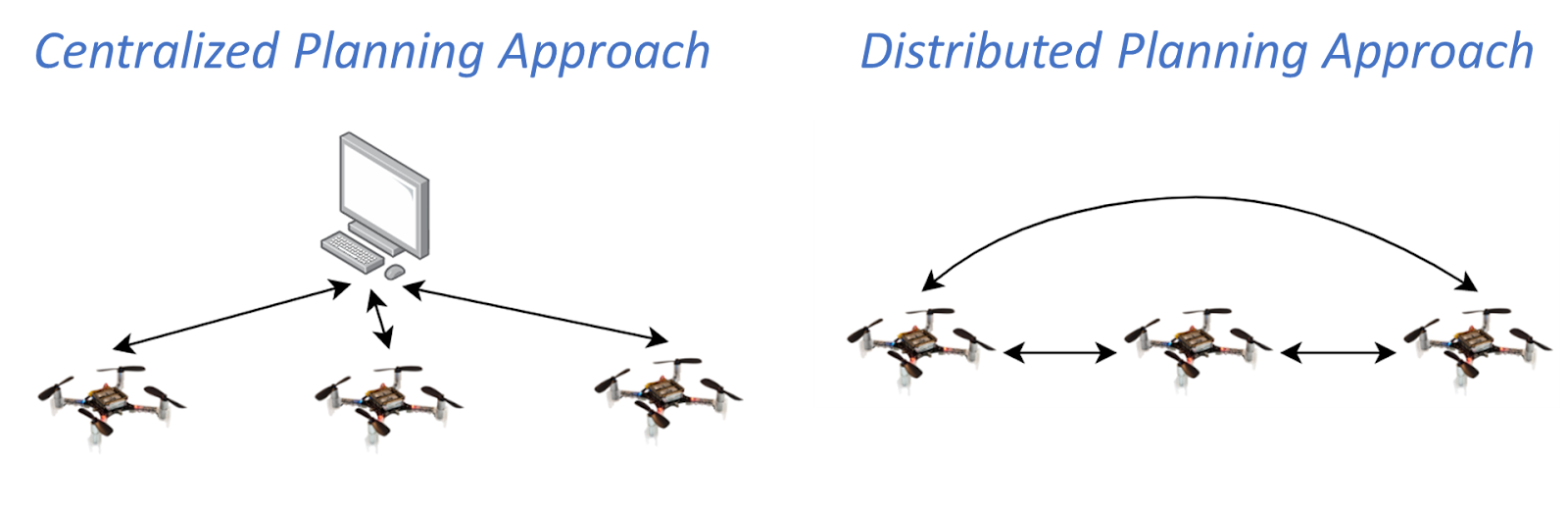
There are two literature groups in the domain of optimization-based quadrotor swarm motion planning: centralized and distributed approaches. In a centralized setup, a central computer solves a joint optimization problem that computes trajectories for all quadrotors at once. These approaches have broad solution space but quickly become computationally intractable as the number of quadrotors increases. On the other hand, the distributed approach involves each quadrotor independently solving its optimization problem and incorporating trajectories shared by the neighbouring quadrotors. This strategy offers improved scalability, yet existing distributed approaches struggle in cluttered environments.
Fig. Centralized and distributed planning approach to quadrotor swarm motion planning. The arrows indicate the flow of communication.
In this work, we adopt a distributed planning strategy. The independent optimization problem that needs to be solved by each of the quadrotors in the distributed setup is a non-convex quadratically constrained quadratic program (QCQP). This nature of the problem stems from non-convex and quadratic collision avoidance constraints and kinematic constraints.
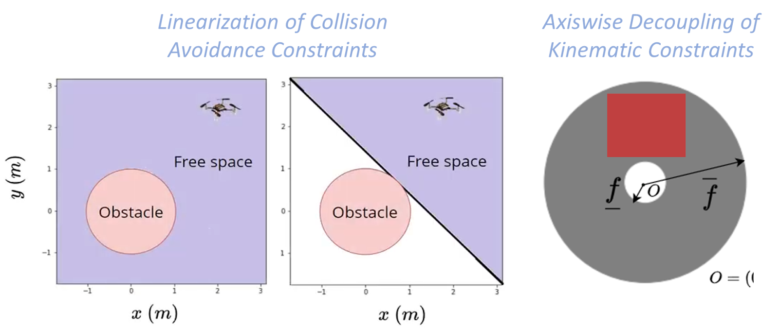
Existing distributed approaches rely on sequential convex programming (SCP) that performs conservative approximations to obtain a quadratic program (QP). First, linearization of the collision avoidance constraints to obtain affine hyperplane constraints. Second, axis-wise decoupling of the kinematic constraints to obtain affine box constraints. We obtain a QP but with small feasible sets.
Fig. Conservative approximations made by Sequential Convex Programming (SCP) based approaches.
Proposed Approach
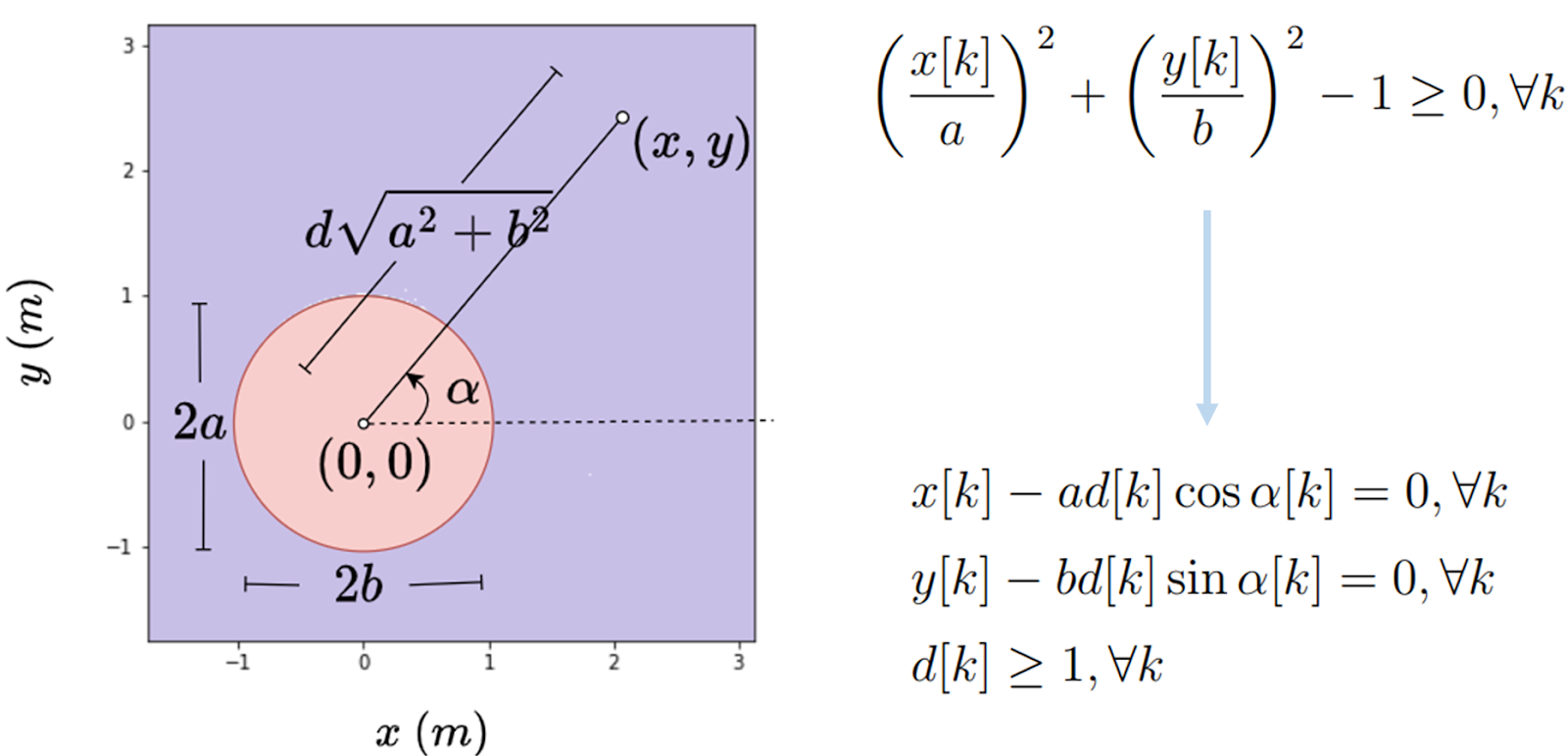
In contrast, our proposed approach obtains a QP without relying on the previously mentioned approximations. The first ingredient is the polar reformulation of collision avoidance and kinematic constraints. An example of the 2D polar reformulation of collision avoidance constraints is shown below:
Fig. Example illustration of polar reformulation of 2D collision avoidance constraints.
The second ingredient is to relax the reformulated constraints as l-2 penalties into the cost function and apply Alternating Minimization. Alternating Minimization results in subproblems that are convex QPs, and some have closed-form solutions, thus obtaining a QP form without relying on linearization; further details can be found in our paper [3]. We can also use and reformulate alternative collision avoidance constraints, barrier function (BF) constraints
where hij is the Euclidean distance between quadrotor i and quadrotor j, and the parameter γ controls how fast the quadrotor i is allowed to approach the boundary of quadrotor j.
Results
We experimentally demonstrate our approach on a 12 Crazyflie 2.0 swarm testbed in challenging scenes: obstacle-free, obstacle-rich, shared workspace with a human. The experimental video is provided below:
In the simulation, we compare our approach against two SCP approaches: SCP (Continuous) [2] enforces constraints across the entire horizon, while SCP (On-demand) [1] enforces only on the first predicted collision. Our (Axiswise) includes box kinematic constraints, while Our (Quadratic) preserves the original quadratic constraints.
From our simulation results, we see that SCP (On-demand) has a lower compute time than SCP (Continuous), as SCP (On-demand) enforces fewer constraints. But, this compute time trend comes at the expense of success rate. On the contrary, our approaches achieve a high success rate with low compute times. Ours (Quadratic) has a slightly higher success rate than Ours (Axiswise) as it has access to large kinematic bounds.
Fig. Simulation results from 100 start-goal configurations with swarm sizes ranging from 10 to 50 in a cluttered environment with 16 cylindrical static obstacles.
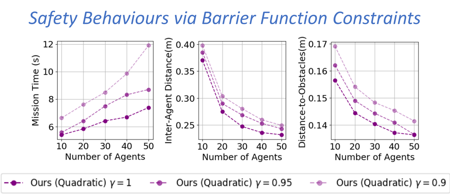
Fig. Simulation results from 100 start-goal configurations with swarm sizes ranging from 10 to 50 and three different γvalues in a cluttered environment with 16 cylindrical static obstacles.
On average, our approaches achieved a 72% success rate improvement, a 36% reduction in mission time, and 42x faster per-agent computation time—our approach trades-off mission time with inter-agent clearance and distance to obstacles via BF constraints.
Outlook
In this work, we presented an online and scalable trajectory planning algorithm for quadrotor swarms in cluttered environments that do not rely on the linearization of collision avoidance constraints and axis-wise decoupling of kinematic constraints. We do so by reformulating the quadratic constraints to a polar form and applying alternating minimization to the resulting problem. Consequently, our planner achieves high scalability and low computation times than existing approaches. We also show that we can reformulate barrier function constraints to introduce safety behaviours in the swarm. One of the future works is to extend the approach to navigate the swarm in a complex 3D environment.
References
[1] Luis, Carlos E., Marijan Vukosavljev, and Angela P. Schoellig. “Online trajectory generation with distributed model predictive control for multi-robot motion planning.” IEEE Robotics and Automation Letters 5.2 (2020): 604-611.
[2] E. Soria, F. Schiano and D. Floreano, “Distributed Predictive Drone Swarms in Cluttered Environments,” in IEEE Robotics and Automation Letters, vol. 7, no. 1, pp. 73-80, Jan. 2022, doi: 10.1109/LRA.2021.3118091.
[3] V. K. Adajania, S. Zhou, A. K. Singh and A. P. Schoellig, “AMSwarm: An Alternating Minimization Approach for Safe Motion Planning of Quadrotor Swarms in Cluttered Environments,” 2023 IEEE International Conference on Robotics and Automation (ICRA), London, United Kingdom, 2023, pp. 1421-1427, doi: 10.1109/ICRA48891.2023.10161063.
The authors are with the Learning Systems and Robotics Lab at the University of Toronto and the Technical University of Munich. The authors are also affiliated with the Vector Institute for Artificial Intelligence and the University of Toronto Robotics Institute (RI) in Canada and the Munich Institute of Robotics and Machine Intelligence (MIRMI) in Germany.
Feel free to contact us with any questions or ideas: vivek.adajania@robotics.utias.utoronto.ca. Please cite this as:
@INPROCEEDINGS{
adajania2023amswarm,
author={Adajania, Vivek K. and Zhou, Siqi and Singh, Arun Kumar and Schoellig, Angela P.},
booktitle={2023 IEEE International Conference on Robotics and Automation (ICRA)},
title={AMSwarm: An Alternating Minimization Approach for Safe Motion Planning of Quadrotor Swarms in Cluttered Environments},
year={2023},
pages={1421-1427},
doi={10.1109/ICRA48891.2023.10161063}
}
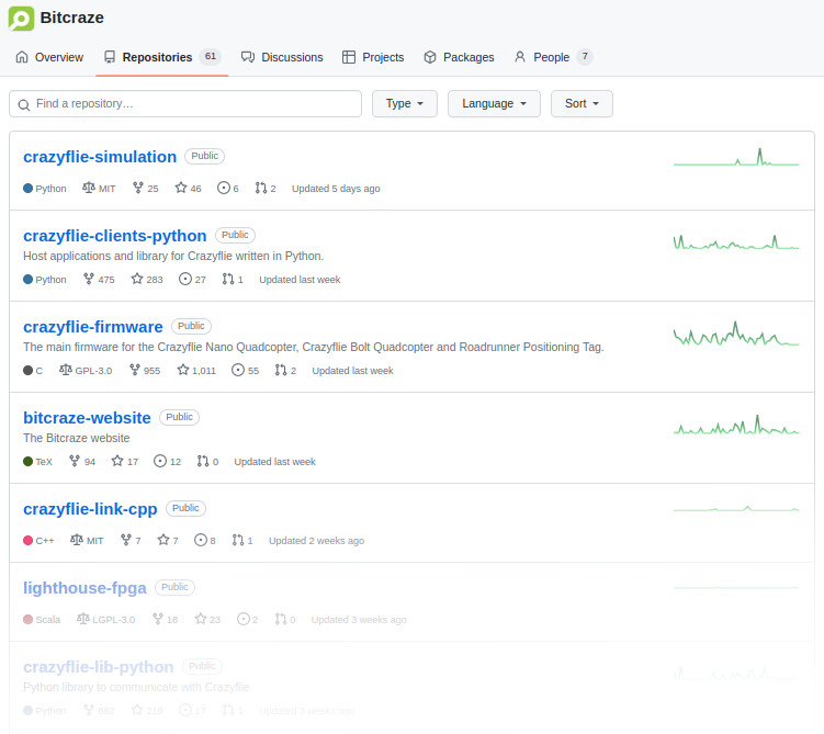
The Bitcraze organization page on github contains some 60+ repositories and if you are looking for a specific piece of code it might be hard to know where to find it. In this blog post we will try to describe how the repositories are organized and hopefully make it easier to understand where to start your search.
The Bitcraze repositories contain code and information related to a wide range of applications and products, some might be of interest to many users, while others have a smaller audience. Examples are software for the Crazyflie and decks, but also things like simulation, tests, hardware and our web site. As we try to be as open as possible most of the content we produce will end up in a repository, which obviously increases the number of available repos over time. For most users there is usually only a handful of repositories that are of interest though so let’s create some order.
The main repositories
There are three repositories that are the hot spots of most functionality, these are usually the first place to look and the only repositories most users will ever use. You can find quick links to these repos in the “Pinned” section on the Bitcraze github start page.
The repositories are:
crazyflie-firmware – the source code for the STM processor firmware on the Crazyflie. This is where most of the important Crazyflie functionality is implemented, such as controllers, estimators, motor control and communication with decks. If you want to change a behavior in the Crazyflie itself, look here.
crazyflie-lib-python – the python library used to communicate with the Crazyflie. This is used to control a Crazyflie remotely. Use it if you want to use a script to control a Crazyflie, also contains lots of examples of how to do common tasks.
crazyflie-clients-python – a the python client that is used to connect to the Crazyflie. The client is simply a GUI that uses the python lib to communicate with the Crazyflie. Everything that is done in the Client can also be done by a script using the python library.
Another source of quick links to common and important repositories can be found on our web, on the Repository overview page. This page also contains short descriptions of the repositories.
Related repositories
Many of our products are implemented as multiple sub-systems, perhaps using different languages or technologies and running in separate hardware, in most cases we separate these sub-systems into their own repositories. The rule of thumb is that these repositories are named in a similar way to indicate that they are related, for instance lighthouse-bootloader and lighthouse-fpga that contain code for the lighthouse-deck. However note that in most cases there will also be related functionality implemented in the main repos as well, in the Lighthouse deck case for instance, most of the actual positioning functionality is in the crazyflie-firmware repo while Lighthouse system management is implemented in the lib and client.
Bootloaders
When powering up a CPU there must be a small piece of code available that sets up the basic configuration of the device to enable it to communicate with other parts of the system, like memories and such. This code is usually called a bootloader. Bootloaders are rarely changed and in most cases written to the device as a part of the factory production process. They have their own repositories and you can find a bunch of them, named XXXXXX-bootloader. Bootloaders are not that interesting and can be ignored by most users.
History
Some repositories might have names that do not make sense in the current context, this is most likely due to historical reasons. We might have given a repository a name that seemed to be descriptive at that time, but as time goes by it might not be as good any more. An example is the range of “LPS-XXXXX” repositories that contains code for the Loco Positioning System. Originally LPS meant “Local Positioning System” as this was the only positioning system we had, but when we also created the Lighthouse system we changed the meaning of LPS to “Loco Positioning System”. A better naming of the repositories would perhaps be “Loco-XXXX”?
A similar transition also exists for the Crazyflie that has evolved from Crazyflie 1 to Crazyflie 2.0 and 2.1. Some repositories (named “crazyflie-XXX”) were created when Crazyflie 1 was released and have evolved to be compatible with Crazyflie 2.X, while some other repositories (named “crazyflie2-XXX”) were created when Crazyflie 2.0 was released. Even though crazyflie-firmware is not compatible with Crazyflie 1 anymore, it still has the old name.
Retired code
Some repositories are obsolete, maybe they contain experimental code that is no longer of interest or perhaps the functionality has been implemented elsewhere. We try to archive these repos and if you are looking for current functionality you can safely ignore any repository that is marked with the “Public archive” flag in github.
Still unclear
There is a short description in each repository that is intended to describe the contents. It is possible (likely) that the description was written a long time ago, with a different context and that it might not be as helpful as intended. If this is the case, just ask us. Drop a question in our discussions forum or send us an email, we try to help as much as we can!
As of this year around March/April we started with both Bitcraze developer meetings and Aerial-ROS meetings (the latter in collaboration with Dronecode Foundation). Now that summer is around and our office is a bit empty, we had a bit of a summer break, however we will start the meetings back up again soon! The next ROS-aerial meeting will be on the 16th of August and we will also have a Bitcraze developer meeting planned on the Wednesday the 6th of September (keep an eye on our announcements in discussions). In this blogpost we like to take the opportunity to show an overview of the meetings we had so far.
Aerial ROS meetings
In March we started a [ROS community working group] for aerial Vehicles together with our friends at Dronecode foundation, aka Aerial-ROS! We have biweekly meetings with some standard discussion meetings (with a topic) and with an invited guest presentation.
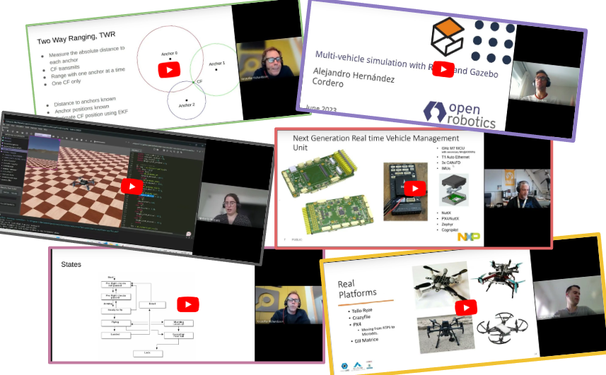
We already had a couple of developer meetings before but we started recording them since April. The first recorded one was about the loco positioning system. Here first we gave a presentation about the system itself, with the latest developments cooking in our pot and time for questions afterwards.
Dev meeting about Loco positioning.
Then we had a meeting about the development of safety features in the Crazyflie in light of the Bolt developments:
Bitcraze Dev meeting about Safety features.
Then we had a meeting where Kristoffer highlighted the autonomous swarm demo we showed at ICRA 2023.
Bitcraze dev meeting about the autonomous swarm demo
And the last before the summer holiday, we had a meeting where Kimberly explained about the Crazyflie simulationmodel intergrated into Webots
Bitcraze Dev meeting about Simulation
We are still planning to have developer meeting every first wednesday of the month starting with September 6th (keep an eye on our announcements in discussions).
EPFL 101 Crazyflie presentation
Oh yeah, by the way, we also were invited by the EPFL-lis lab to give another Crazyflie 101 presentation in Lausanne last April! We made a prerecording of it so you can check it out right here:
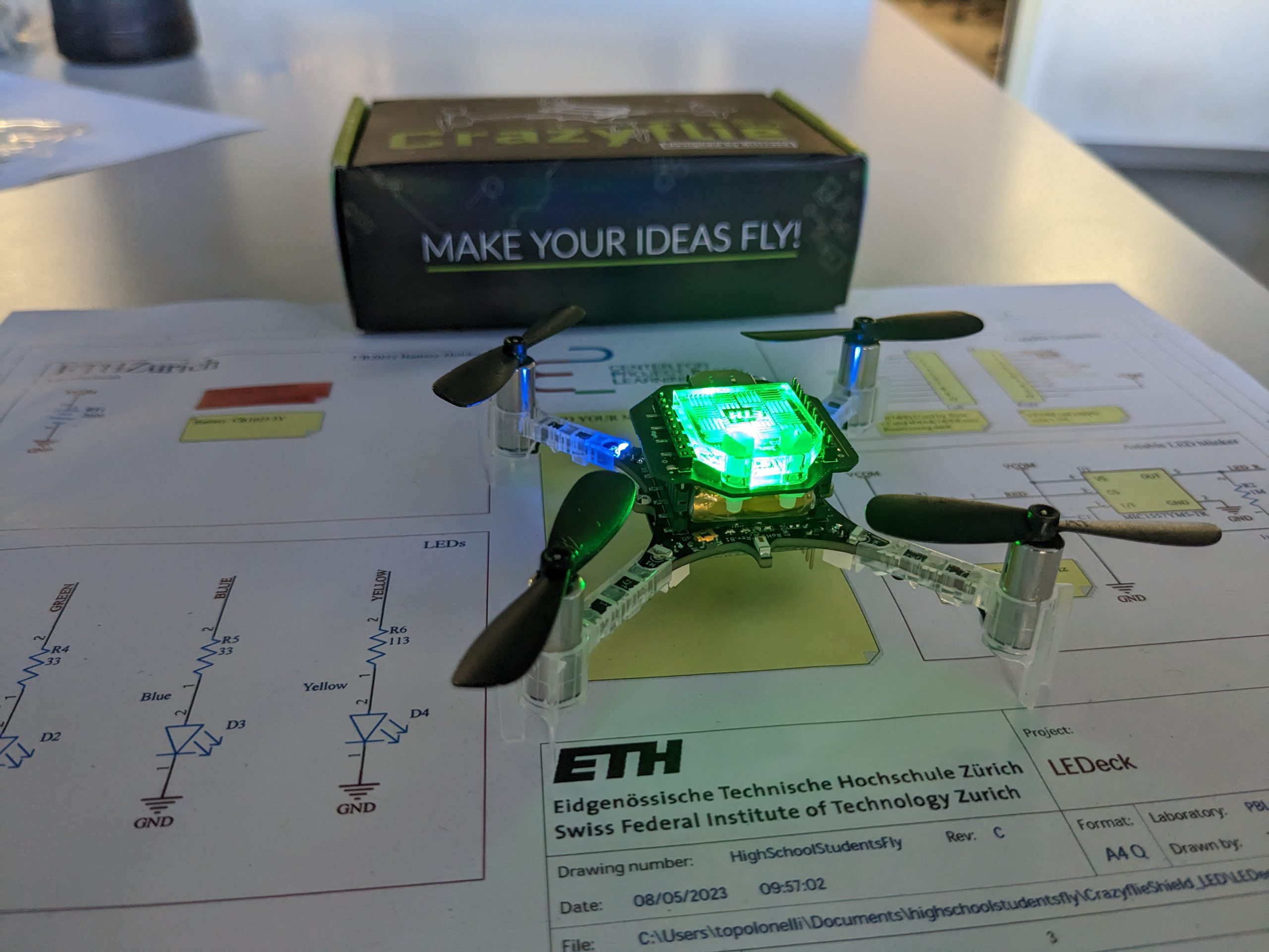
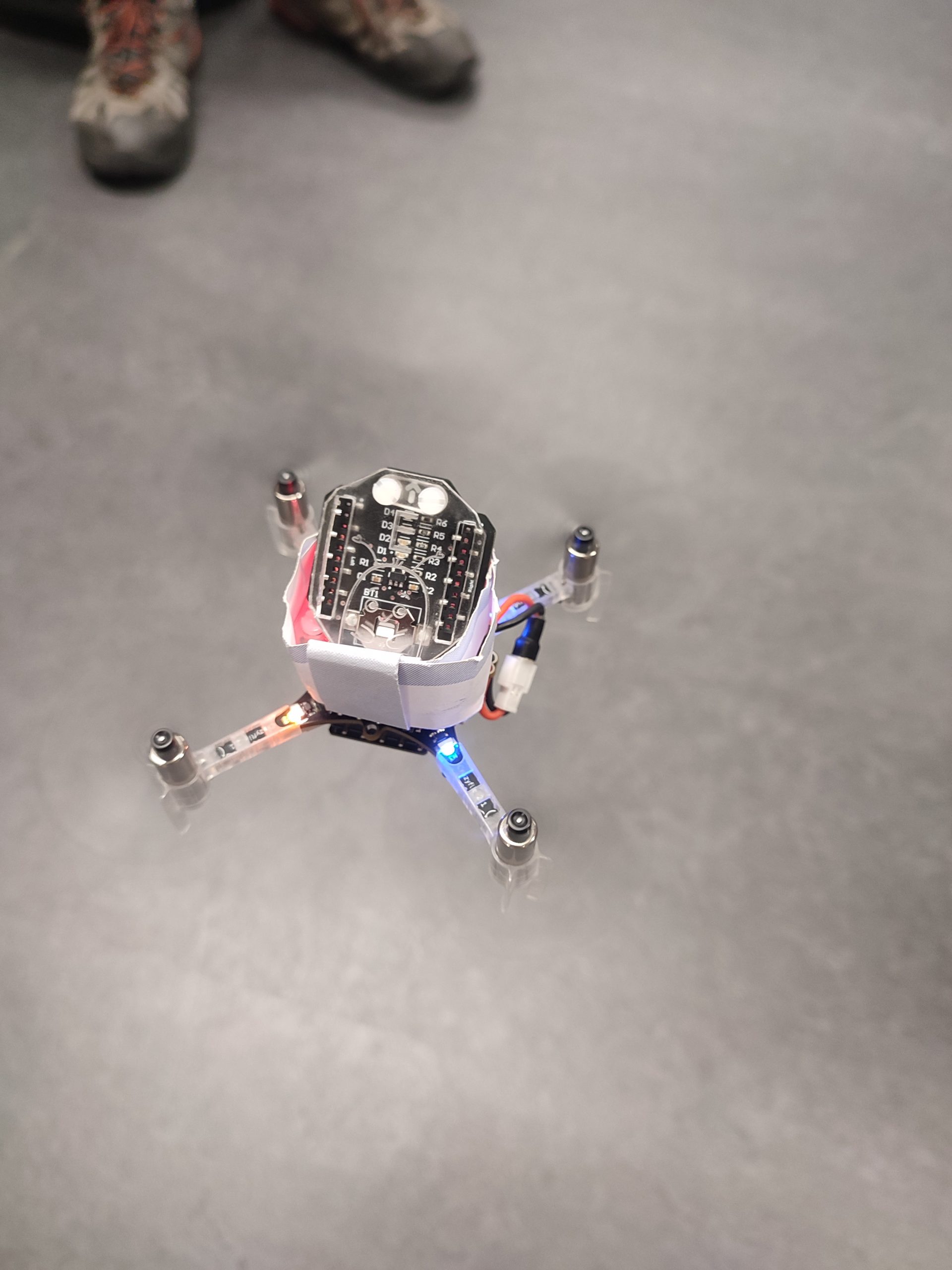
This early summer my research group (Center for Project-Based Learning at ETH Zürich) was in charge of a special week – high school students from all over Switzerland (actually even the world, they had to speak German though) could apply for a study week at different departments from our university. The departments which joined this initiative were mathematics, physics, biology, environmental sciences, material sciences, and our department, electrical engineering and information technologies (ITET). But how do you show teenagers between 15-19 in one week as much as possible from electrical engineering while also having fun? And best inspire them to study at ITET? Our solution was: drones. More specifically, Crazyflies. With those we had many possibilities to learn about electrical engineering – from sensors, microcontrollers, timers, and motors to LEDs, batteries, embedded systems, FreeRTOS tasks, state estimation, and controller – and all this with a high fun potential and a low risk of accidents, as with their weight of only 30g they hardly ever do any damage. In this blog post, I will guide you through our week, in hopes to help others who also want to use the Crazyflie to teach students about electrical engineering in a fun way.
Monday
We started in the afternoon (in the morning they had a welcoming tour) with a short introduction and splitting the 20 students into groups of two (everyone got a paper slip and had to find the matching one, accelerometer gyroscope, pitch roll, UART SPI, and so on – this gives the lecturer a great opportunity for interaction with the students later on, once their word gets relevant during the week). After a short introduction to programming and microcontrollers we moved on to the most classic beginner task: blink an LED! We chose to use the front left one, as this one is only used when communicating – so as long as we don’t connect to the drone we can observe exactly what we programmed. Most students got the LED turned on rather quickly – however, pulsing the LED to change the intensity took them some more time and forced them to learn how to write loops. They also already learned how PWM works without knowing it yet – setting the intensity of an LED or the strength of a motor is about the same thing in the end after all and this gave us a great start for Tuesday.
Tuesday
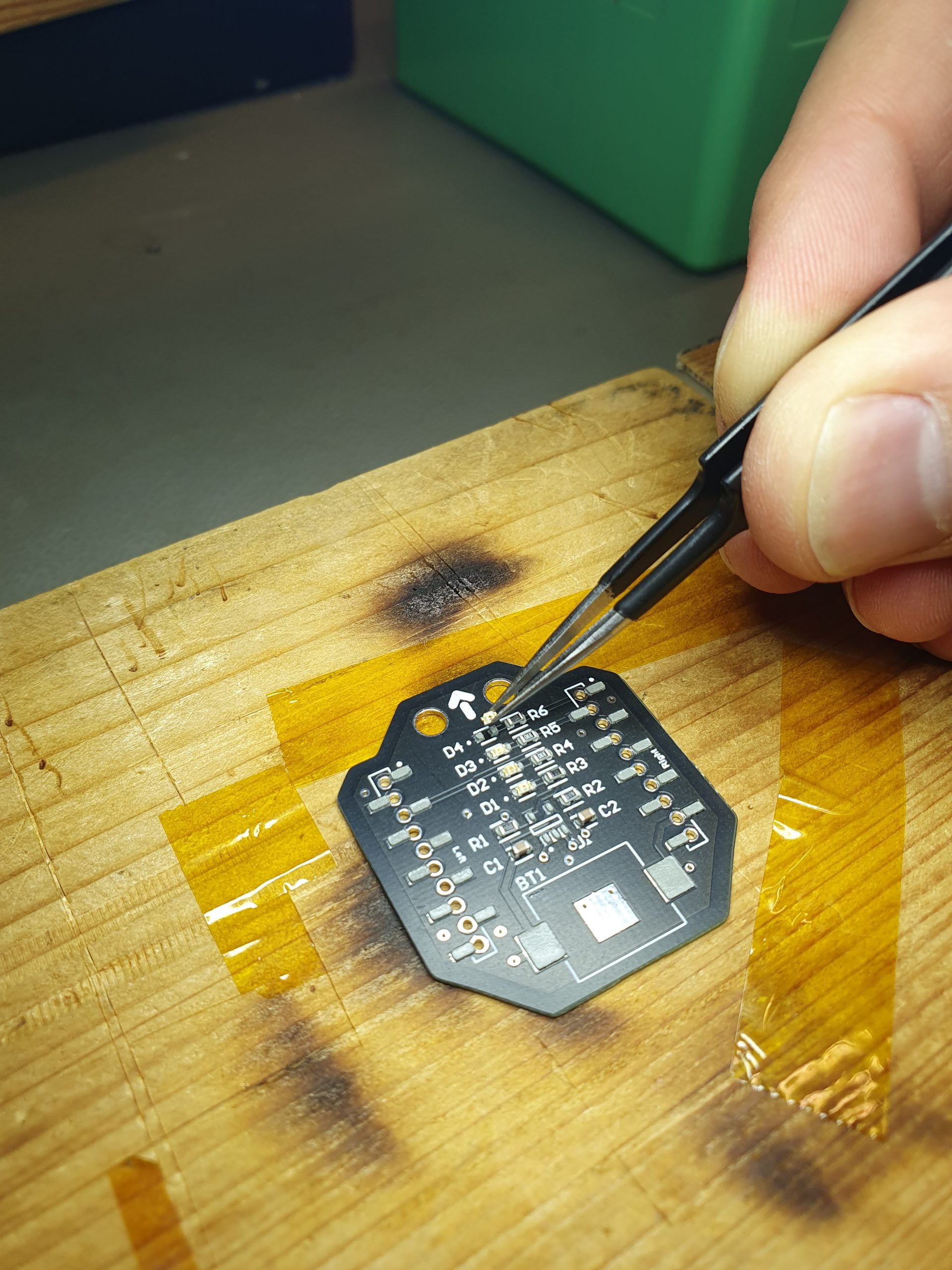
On Tuesday we looked at hardware from different perspectives. As you might have guessed, we looked at motors and how to control them with PWM and timers. The students were a bit disappointed that we still didn’t fly, but as soon as they realized that they could play their favorite song on the motors the motivation was high again! We didn’t even have any stray drones, even though we let them mount the propellers (the songs sound much better with propellers). We also looked at another aspect of electrical engineering: PCB design (this was already done though) and soldering. For this, we prepared a custom deck, with four colored LEDs, which could be populated like in industry with solder paste and then soldered with a hot plate. To make it even more fun (and partly to show off our laser cutter) they also designed a small plastic diffuser that could be mounted on top. So in the end our setup resembles the LED ring – however, it can be mounted on top which is essential if you don’t want to fly with a positioning system (and therefore need to mount a flow deck).
Wednesday
Trying out the state estimation
Now that we knew how to blink LEDs and, even more important, how to control motors we had to learn a bit about how the drone actually figures out which motor should be turned on and how much. For this, we first looked at sensors and wired communication protocols, such as I2C (for the IMU and time-of-flight sensor), SPI (for the optical flow), and UART (to the nRF) – due to limited time we didn’t go into details here though. We briefly touched wireless communication, to explain how the commands they will later send to the drone (and the firmware) are actually sent to the right drone.
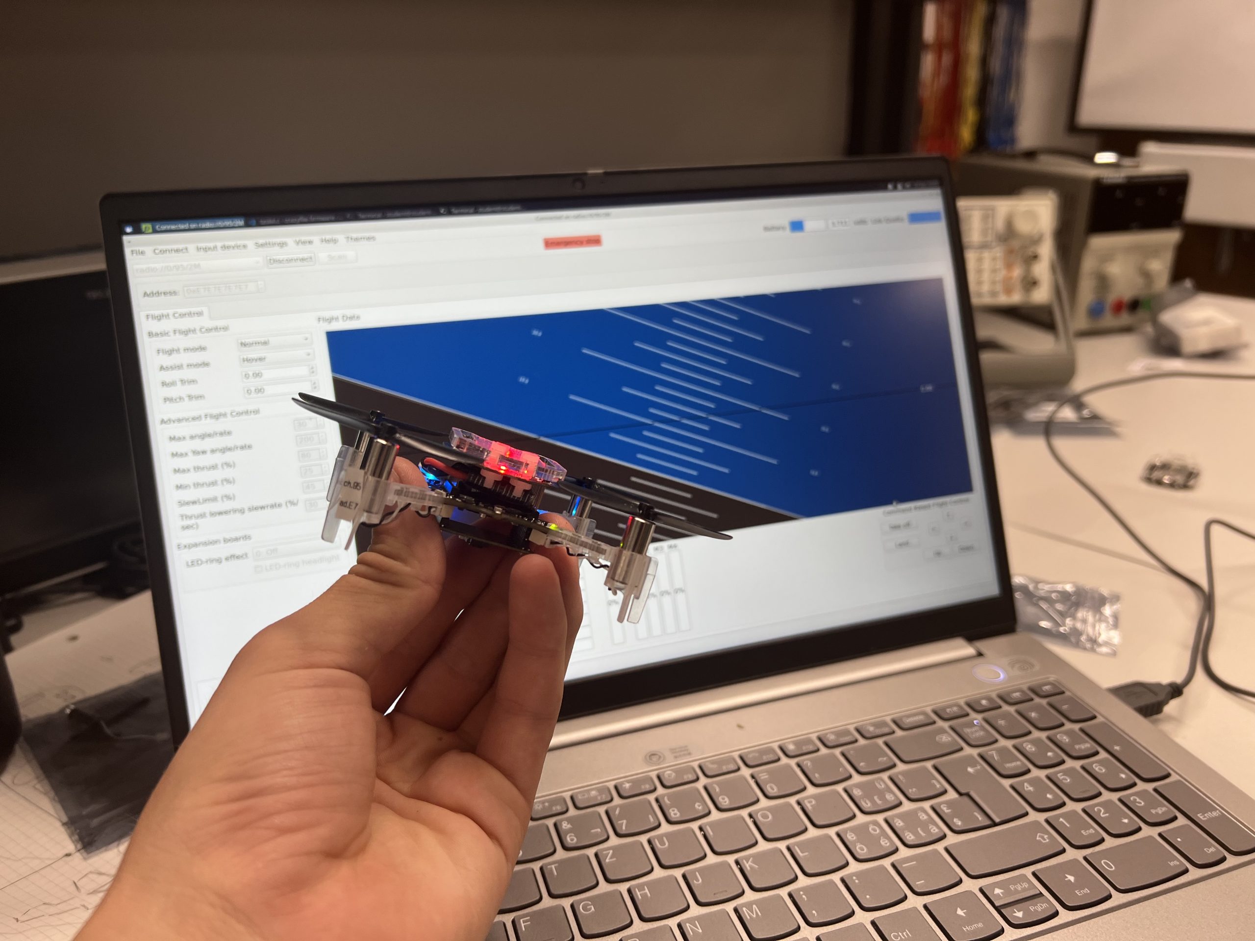
Tuning PIDs
We moved on to what state estimation is in general – again jumping over all details of an extended Kalman Filter, but had a closer look at the logging and parameter system. We then spent a bit more time on the PID controller again – which was also a bit hard to explain, as half the teenagers hadn’t learned how to integrate and differentiate yet. However, they learned fast and we could move to the part they waited for all week long: Flying (and tuning the PID).
Thursday
Transport drone
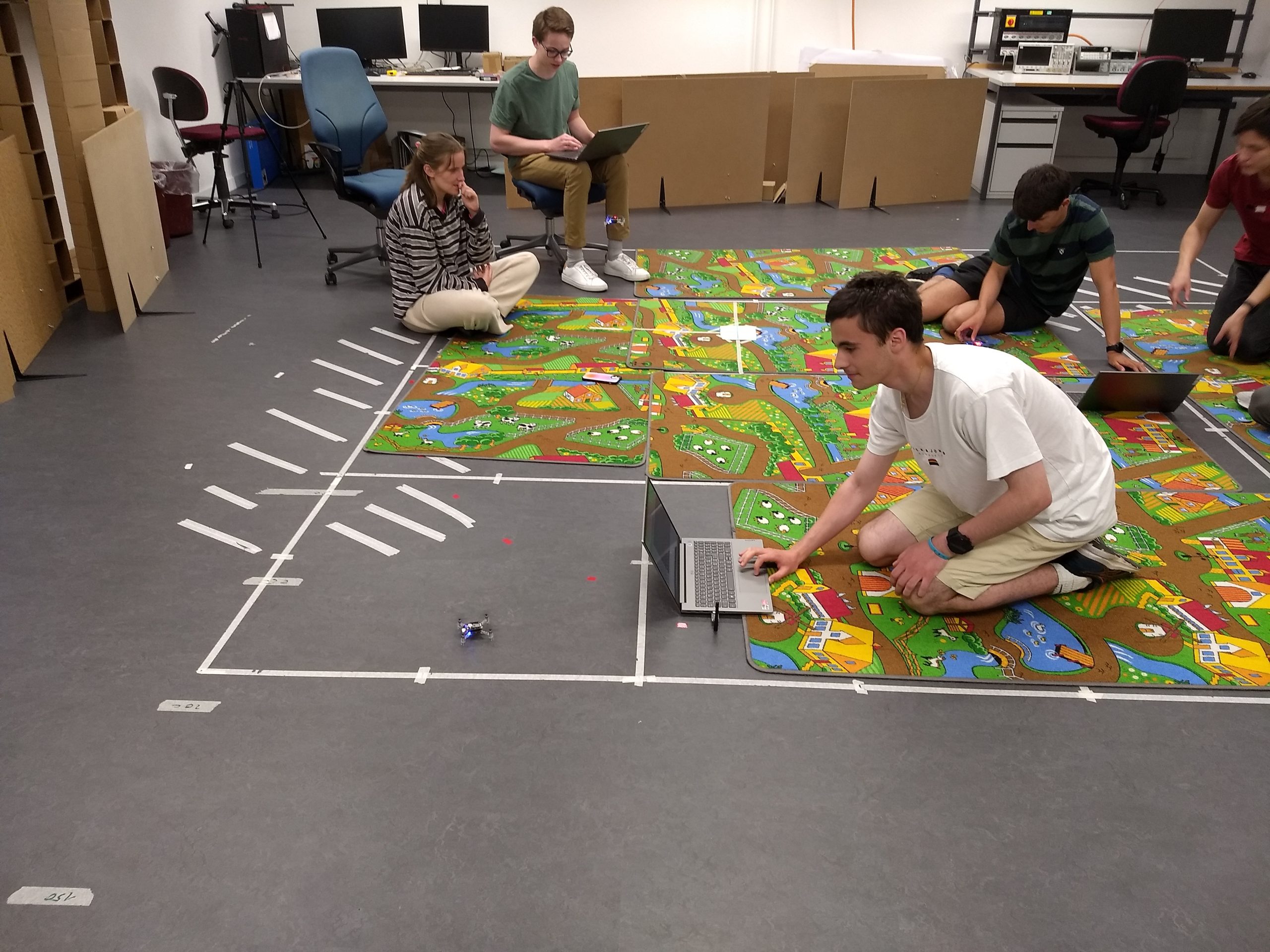
This was the day that was meant for creativity – the students could choose themselves which project they want to achieve. We proposed them some ideas, such as blinking LEDs depending on the height, flying through a gate (the challenge here is to filter the height measurements when the gate border is below the drone), steering the drone with the keyboard, soldering an own sensor on a break-out board, …
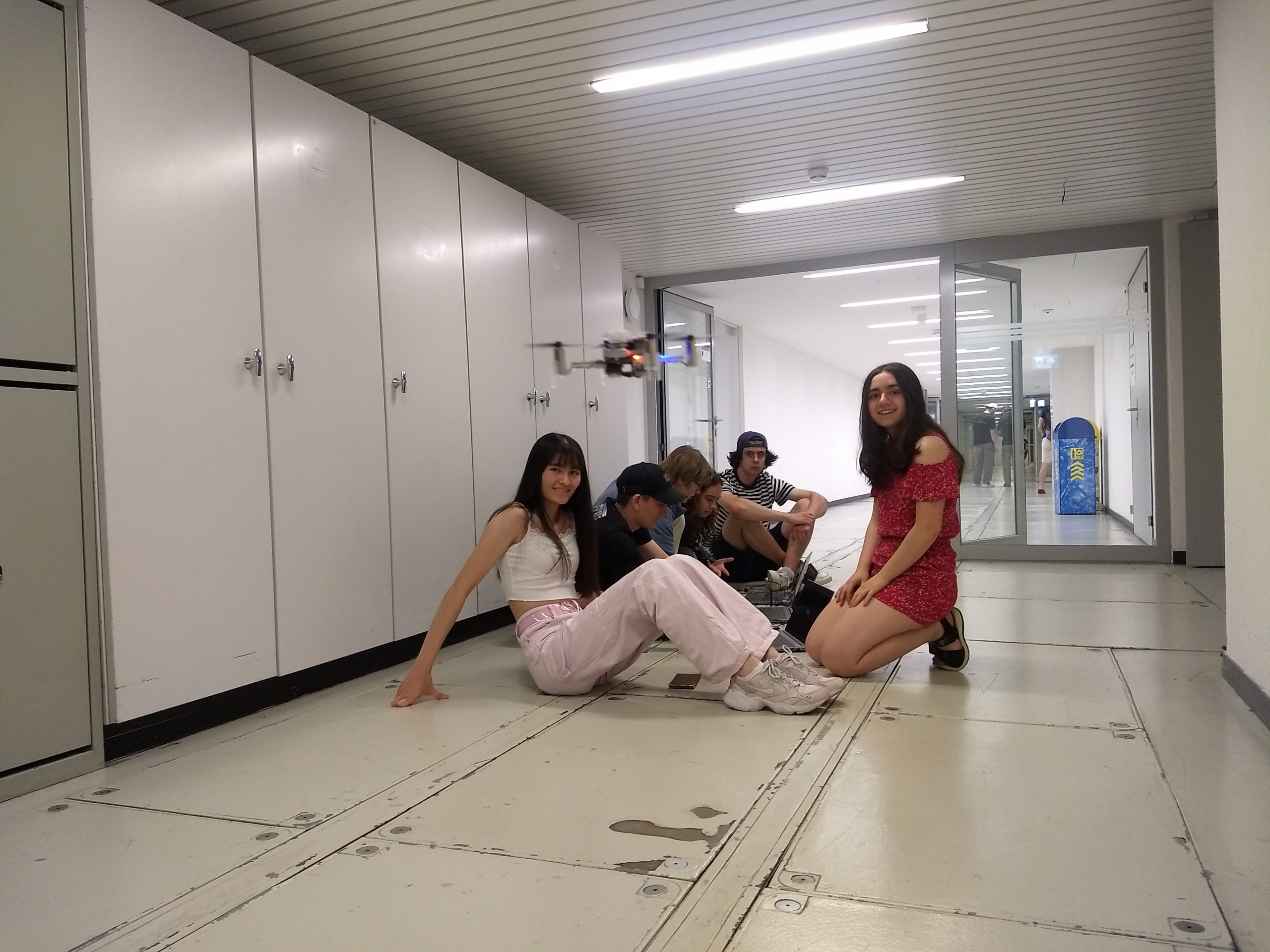
In the end, we saw many cool projects, from a song played as a canon on multiple motors to a transporter drone, flying successfully through the gate, doing a successful looping (unfortunately no successful landing yet…), racing against each other (possibly with disco-lights on the deck) and trials for reaching max speed in the hallway.
The hallway was very popular to fly, as the distance to accelerate was longer…
Practice on the race parkour
The most popular base project was to steer the drone with the keyboard – unfortunately (or fortunately? they sure had fun with it once it was running and they might have learned enough in the remaining week…), this was very easy after we showed them where Marcus’ script lives (here) and which 8 lines (170-177) they have to remove for it to work without an AI-deck (and don’t forget to adapt the URI)…
Friday
Quite an audience!
Flying was forbidden – but playing music with motors was not!
On Friday it was presentation day – in the morning they could still work on their projects, but in the afternoon all the 120 students (and most of their parents) came together in a huge lecture hall to present what they did during this week. And, as at a real conference, they had posters and their drones (which we, unfortunately, were not allowed to fly without a fireproof net… Will organize this next time) to show their projects to family, friends, and even random tourists (the entrance hall of the ETH main building is on many sightseeing tours).
At the end of the week I doubted the robustness of Crazyflies for a moment – however, Monday morning once I had peace and quiet once again I figured out what was wrong with all hardware which ended up on the “not working for unknown reasons” stack in less than an hour (and fixed almost all of it). Notes to all others and my future self for the next time I give 10 drones to 20 teenagers:
If you show them how to tune a PID, also explain that “persistent” means exactly what it says – if you mess up the PID values and persist them they will stay this way until you reset them, no matter how often you reflash the drone.
Explain how fragile connectors are and that you NEVER should pull at cables. Also, mention 10x more to be careful when plugging in decks. And radios.
Keep one “private” drone no one is allowed to mess with – it will help greatly to figure out if they only broke the flow deck connectors or something more serious (which actually never happened)
Doing only warm boots with setting individual addresses with the CLOAD_CMDS while flashing saved us a lot of trouble, randomly connecting to drones only happened once they discovered the app for the phone…
The coding tasks (and at least some minimal solutions) can be found on my fork: Tasks and solutions. They are kept short on purpose – we at the Center for Project-Based Learning believe in our name – we believe the most learning (and fun) happens when you rather freely explore what you can do with the basic tools you just learned.
P.S. For completeness – I cut out all the parts which really had nothing to do with Crazyflies, we also did lab tours in the high-voltage laboratory and the laboratory for optical communication – and of course had some social events with actual university students. As much as we like the Crazyflie, even we have to admit that the field of electrical engineering is even bigger than what we can show with those tiny drones ;)
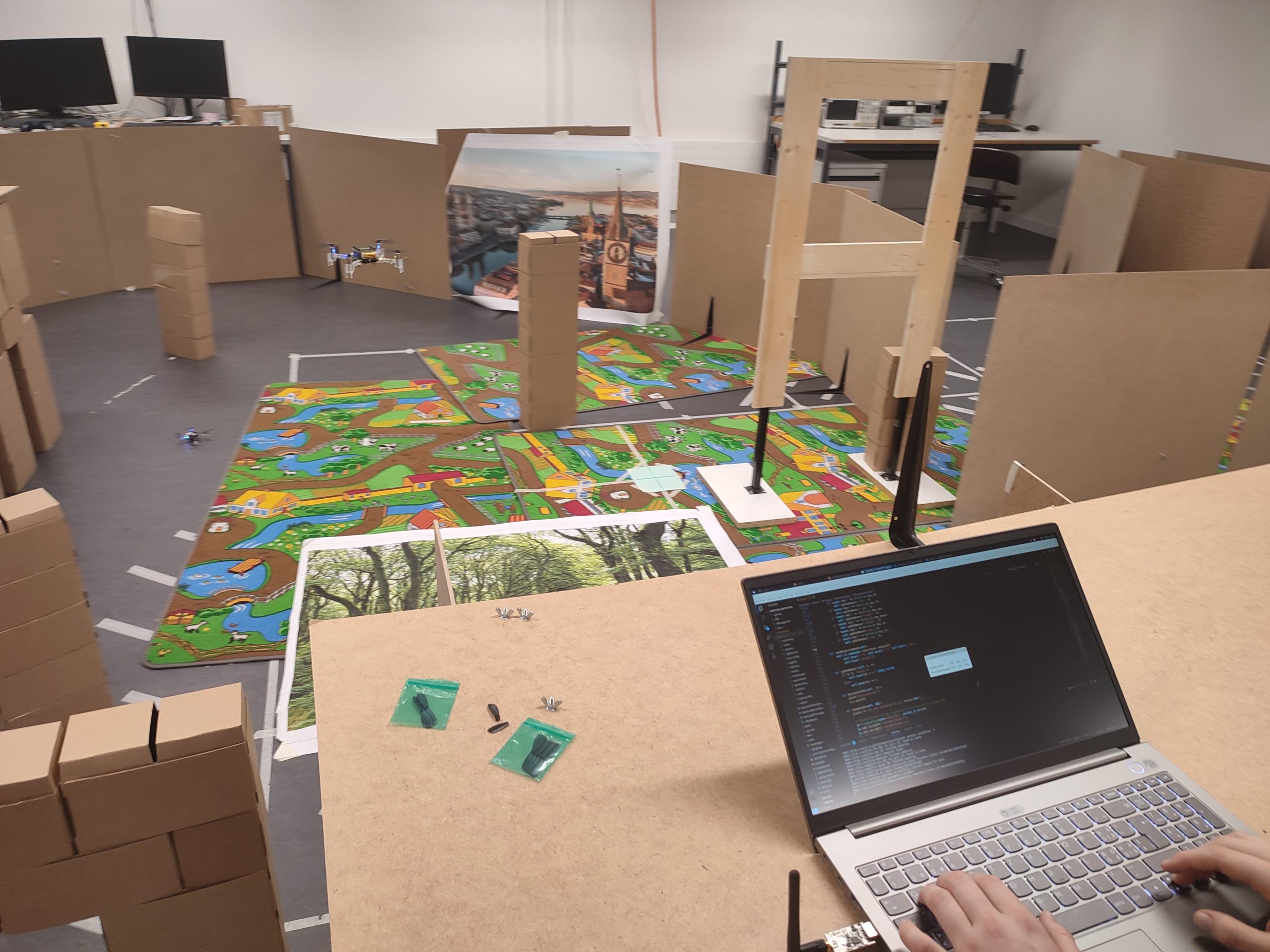
When the Crazyflie was created the intended use case was manual flight with one drone. Over the years we have added support for positioning, swarms, autonomous flight and all sorts of nice features, and it has all been built on top of the original code base. Some of the original code is actually untouched after 7-8 years and needless to say, there is a slight worry that we might have taken design decisions back then that will come back and bite us in new use cases. This blog post will outline some of the work we have been doing to handle this problem by setting up an autonomous system where a Crazyflie is continuously flying – the infinite flight project.
The original design essentially assumed one Crazyflie that is controlled by one computer with one Crazyradio. On the computer the user was running the python client and controlling the flight manually with a game pad. The user might have restarted the Crazyflie before each flight, or at least when changing battery.
Now fast forward to the current situation where a swarm of Crazyflies might be controlled by multiple radios, each connecting to multiple Crazyflies. The Crayflies are flying autonomously, perhaps getting their current position from the Lighthouse system, or via radio based on information from a mocap system. Maybe telemetry data is sent back to the ground while commands for trajectories to the Crazyflies go in the other direction. In some systems the Crazyflies use wireless charging to be able to run continuously.
Obviously the current situation is very different from the original design with new or changed requirements. One is the extended use of the radio, and this is something that we have been talking about in some previous blog posts and we will not discuss that here. This blog post will instead be about one other important topic: long term stability.
In the original design, the Crazyflie was restarted often, maybe before each flight. This means that the code did not run for a very long time, so what happens if we use wireless charging and keep the firmware running for days? Will there be a problem? We decided to find out by starting an internal project we called “Infinite flight”. The idea was to set up a system with a Crazyflie with a Qi-charger for wireless charging and a Lighthouse deck for positioning. An app in the Crazyflie takes off, flies a trajectory and lands for recharging when the battery is out, the cycle is then repeated for as many times as possible. By doing this, we hoped to find any software problems in the firmware that might show up after some time, finding hardware that is worn out over time or other finding other issues. Spoiler alert: we have not reached infinity yet, but we have got a bit closer :-)
The setup is fairly straight forward, the firmware is based on the app used in the demo we used at IROS and ICRA, with some modifications. We have a ground station computer that collects data, it tries to continuously maintain a connection and re-establish it if it is lost. We log as much as possible to be able to analyse problems and understand what happened. We also added some tools to make it easier to visualize and dig in all the log data. The usual work flow has been to
Start the Crazyflie and run the app
Wait for something to go wrong (sometimes days)
Analyze what happened and figure out if something needs to be changed
Update and start over again
A surprising number of runs failed fairly quickly, only after a few flights. The reason has usually been some sort of handling error or problems with the test software, but some have been of more general interest or bugs.
Stopped logging
We had a problem where the logs from the Crazyflie in the ground computer stopped without any apparent reason. It turned out to be related to the session-less nature of the CRTP protocol, there is no good way to determine if a session is alive or not, other than using a timeout. It turned out that there is a timeout in the Crazyflie firmware (that was not fresh in our memories) that stops logging if no packets are received for a while. The rationale is to avoid having old logs running if a client is disconnected. In our case we lost communication for a short period of time and the firmware simply stopped the logging. The python lib on the other hand had a longer timeout and did not have the view that the connection was lost. The solution we used is to set up the logs again if we don’t receive logging for a while (we fixed an issue in the python lib related to this)
In the future com stack we plan to have proper session handling which should remove this problem.
Controller tuning
We have been using various flavors of Crazyflies in the tests, including some prototypes. We had some issues with one prototype that we did not understand, it had a hard time hitting the landing pad when landing. It turned out that the STM that was used in the prototype was reused from an old Crazyflie and it had some weird PID controller settings stored as persistent parameters. With the persistent parameters cleared, it worked as expected.
We have played a bit with tuning the controller, but the default settings are fairly OK and we used them most of the time.
Some of the prototypes we used had some glitches or irregularities, it is very hard to hand solder PCBs. These problems are only related to a specific hardware individual and can cause some unexpected behavior which takes time to figure out.
Landing pad edge
The landing/charging pad we use (also used in our demos) generally works fine, it has a “slope” towards the center which helps the Crazyflie slide to the correct position. If the Crazyflie miss the landing too much though, it will end up on the edge with one leg on the ground and an angle away from the center. In this case it sometimes fails to take off properly and crash. We solved this by adding a foam pad around the landing pad to “raise” the surrounding floor the the same level as the landing pad and thus reduce angle.
Lighthouse bug
There is a known bug in the lighthouse deck that prevents it from receiving data at certain angles. We had some cases where our landing pad was located in a spot where we lost tracking of both the active base stations for some yaw angles. If the Crazyflie happened to land in that exact yaw angle, it lost the position while charging and it did not know its current position when it should take off again. This was solved by moving the landing pad to a different position.
Not yet investigated possible problems
One possible known problem is the system tick counter in FreeRTOS. The counter is a 32-bit unsigned word and it is increased every millisecond. The counter is used in the firmware as the internal “clock” to determine for instance how long ago the estimator was updated or to determine when to execute some piece of code the next time. This counter will wrap after 2^32 ms, that is around 7 weeks, and we don’t really know what will happen.
Results and conclusions
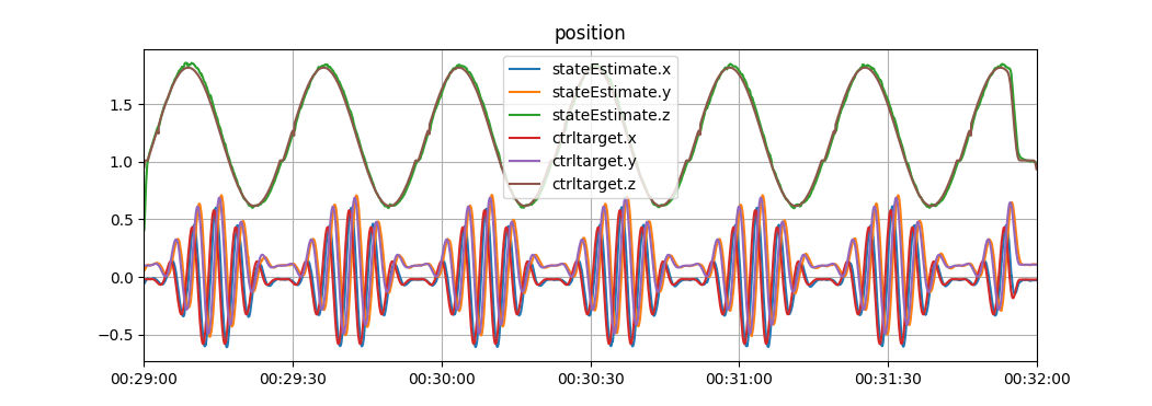
The longest we managed to keep the system running was 5 days. We had a slow charging cycle and only flew 57 times. In this session, the flight time was very stable between 5:30 and 5:45 for all flights. This test was done with a standard Crazyflie 2.1 with a motor upgrade kit.
The second longest session was 3 days, in this case we used a brushless prototype and pushed the charging very hard. We ended up doing 276 flights but the battery was pushed beyond specs and being too warm and charged too fast, it degraded over time and the flight time was reduced to only 2-3 minutes at the end.
We believe we have fixed most of the long term stability issues, but it is hard to know. There might be bugs lurking in the firmware that only show up under very special conditions. What we do know is that it is possible to fly for 5 days!
It’s summer here in Sweden, which means a lot of sun, heat, and… well, right now, rain, but hopefully things will get better.
Credits: Silvia Man/imagebank.sweden.se
As every year, we try to enjoy it as much as possible. That means that some of us are taking off for well-deserved vacations. During the coming month, Bitcraze will be run by a skeleton crew of people.
That means that the office will get slower too. Now, keep in mind that in a company made by only 6 persons, 3 people going on holidays is taking half the workforce – so the remaining men and women are here to keep things afloat. We will still ship the orders regularly – in a huge part thanks to your new and improved packing system– and answer emails, helping you on Github discussions etc… on a regular basis. But our response time may be slower than usual – and some things will have to be postponed until the right person can get to it. We will, of course, always tell you what’s happening, and keep going with the Monday blogposts.
For us that are in the office, it is also the chance to focus on more personal projects. Often during the summer, when our colleagues are away, we grab the opportunity to develop ideas and projects that we usually don’t prioritize. Last summer, for example, Kimberly dig deeper into ROS2. I myself will try to make some changes to the office itself. We will also try to clean up- not only the office itself, but fixing various bugs that usually don’t get the highest priority. In general, we try to have a clean slate before things start to get back up again.
We hope that you can also enjoy a slower summer and some vacations!
Today, Lennart Bult from Emergent Swarns presents us with this project of a 24/7 swarming demo. Enjoy!
Over the last few months our team has been working on creating a 24/7 swarming demo. Initially tasked by Guido de Croon and Chris Verhoeven from TU Delft MAVLab and the TU Delft Robotics Institute, we set out to find our way within the Crazyflie ecosystem to gradually increase the size and capabilities of the swarm. In this article we will first talk about some of the work and methods that we used. After that, we will introduce the TU Delft Science Centre Swarming Lab and talk about some applications of swarming drones.
Developing the 24/7 swarm
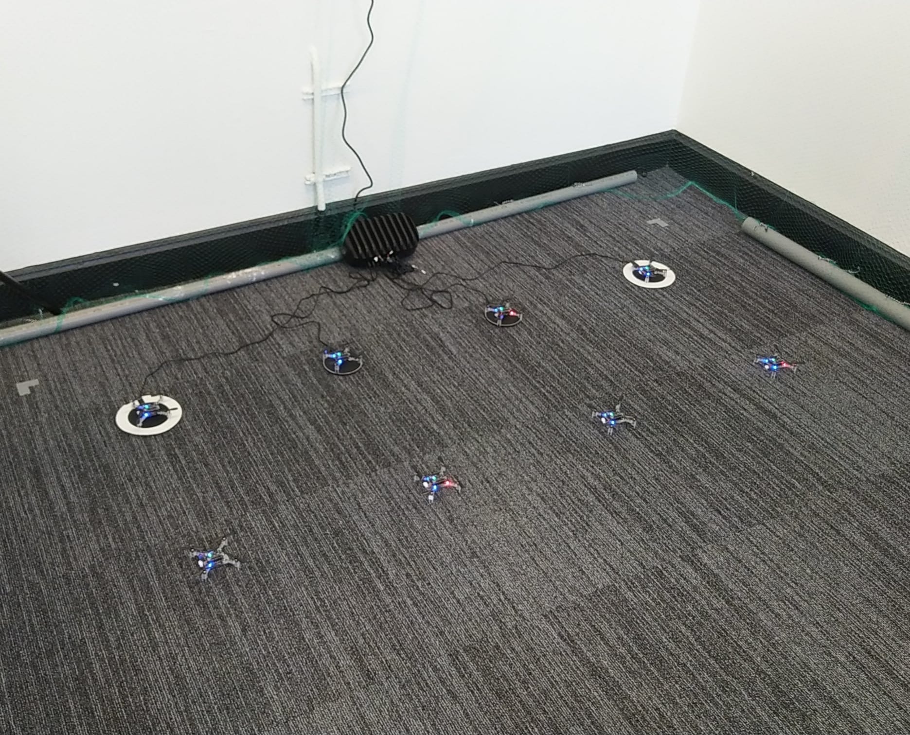
The project started in February with the goal of creating a physical swarm capable of real-time collision avoidance with drones and static obstacles. We started out with three drones equipped with the Flow Deck, and by setting them up in a clever way we could perform the first collision avoidance and landing tests. We were impressed with the performance we got out of the Flow Deck, however, eventually, it is mostly a battle against the drift of the position estimate, that is, we could increase some of the margins on the collision avoidance only so far before we would either fly out of the test zone or collide with another drone. Luckily with short test flights, we were able to see some of the flaws in our algorithms and correct them before testing with the new setup.
Setup after the first expansion to eight drones.
After a few weeks of testing we got approved for the first swarm expansion, five more drones and a Lighthouse positioning setup. This is when we could do our first real tests with the collision avoidance algorithm, which, much to our own surprise, worked on the first try. This is also when we first posted a project update on LinkedIn. There were however a lot of bugs that still needed to be worked out, and a lot of system experience still to be gained. After flying for a bit longer we noticed that some of the drones would flip quite often, which is when we discovered that we needed the thrust upgrade to control the additional weight of the larger battery and charging deck.
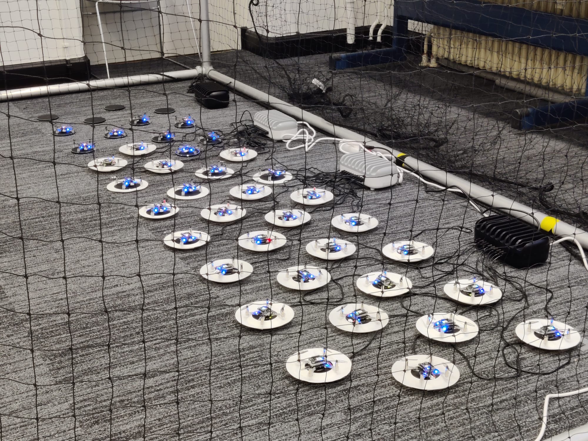
For the charging setup we took inspiration from the Bitcraze IROS 2022 demo; we 3D printed sloped landing pads that we tape onto a wireless charger. After a few iterations we landed on a design that uses minimal printer resources and allows the Crazyflie to land a bit off-center. This last feature turned out to be quite useful considering the large amount of destabilizing airflow that is generated by 40 drones. After receiving the last order of drones we also expanded the charging setup, which at this point takes up quite a bit of floor space. There are some ideas to create a vertical landing pad stack, which would bring the additional challenge of missing the landing pad not being an option.
All 40 drones recharging before their next flight.
After prototyping the charging setup and building confidence with the initial setup, we were confident enough in our system capabilities to expand it to the point where a continuous demo of 5-8 drones is possible. Although the system integration of the previous expansion went without much trouble, we did encounter a few issues when expanding to 40 drones. The first issue of which was radio communication, we noticed that a delay in the radio communication would be present if we increased the update rate above a certain level for a specific number of drones per radio. The second issue we encountered were performance drops related to the violation of certain bounds in the collision avoidance algorithm. These two issues were very difficult to debug since it was not immediately obvious where the source of the issue was.
The third and last major issue was the increase in destabilizing airflow of 40 drones compared to 8. With 40 drones there is a noticeable breeze when you stand next to the drone cage, which is nice for summertime, but not so nice when drones need to land in a tight-packed configuration. To combat this issue there is a limit to the amount of drones that can land at the same time. There is also a minimum separation distance between two active landing pads, which reduced the severity of the induced turbulence. There are still ongoing efforts to increase the landing success rate, which is currently affected by drones running out of power during the landing procedure.
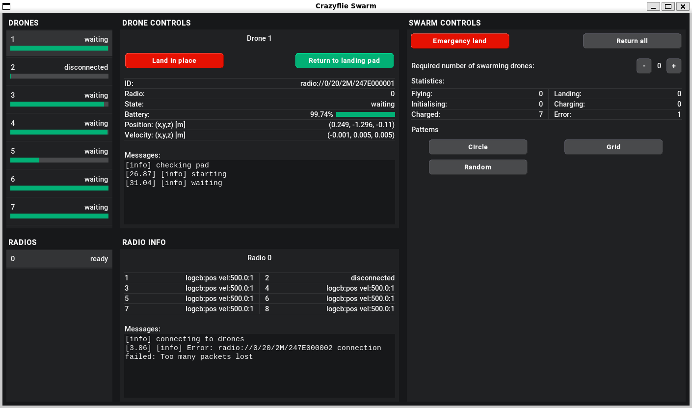
To control and monitor the swarm we designed a custom GUI, an impression of which you can see below. Although some of the buttons are still a work in progress, there are a lot of features that have already proven very useful, especially when testing a new feature.
V1 of the graphical user interface developed for the 24/7 swarm.
The code base that we created for the swarm will be largely open-sourced (only the collision avoidance will not be open-source) to provide researchers all around the world with the possibility to setup their own Crazyflie swarm for research. You can find the repository through this link. Note that the documentation and code base are still under development and might contain bugs/errors.
Human interaction
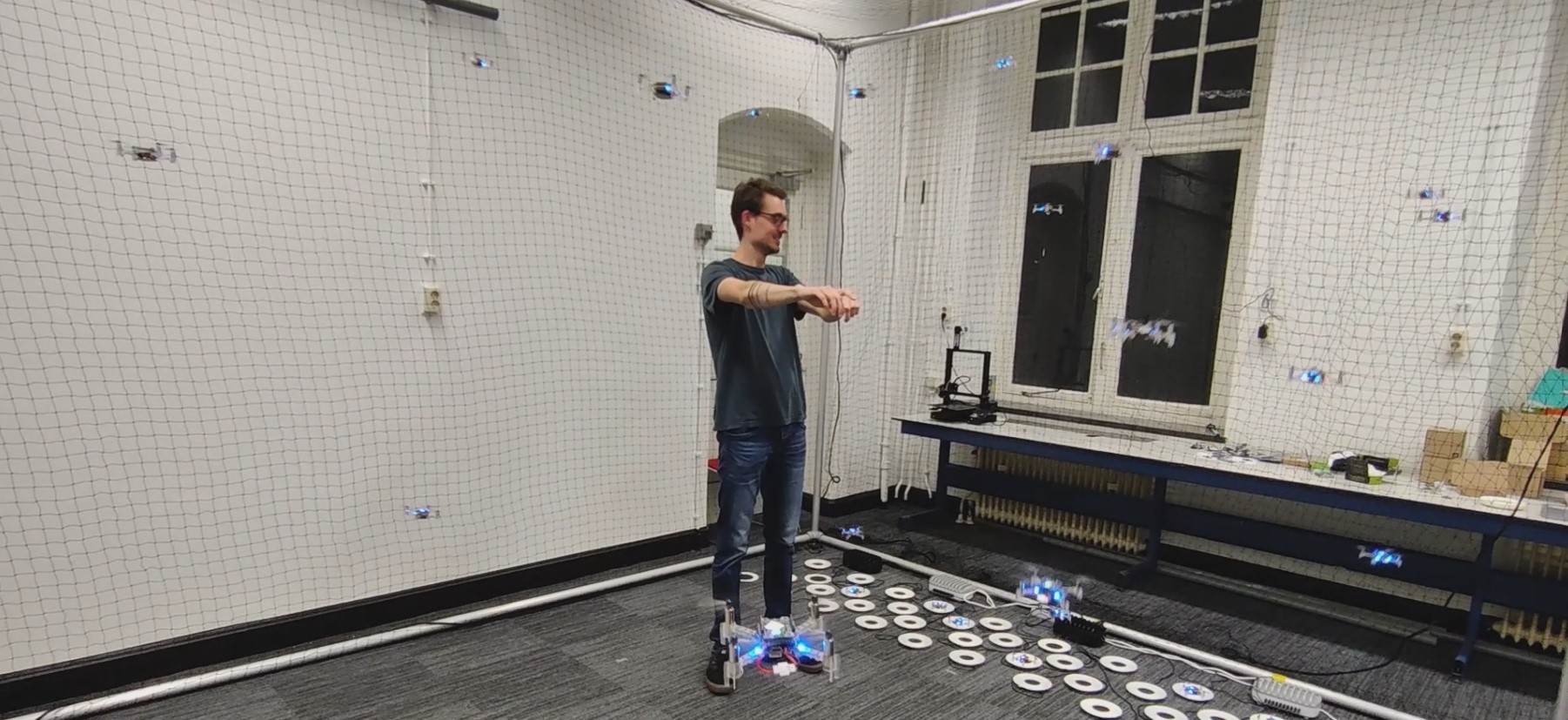
After creating all functionality to provide a continuously operating swarm demo, it was time to work on some of our stretch goals: 1. walking through the swarm whilst it is operating and 2. controlling the swarm using our arms. In the image below you can see an impression of precisely this functionality. The drones are following the operator’s gesture commands whilst performing live collision avoidance with an operator.
Team member Seppe directing the 40 drone swarm, see the full video here.
This demo requires multiple techniques and hardware elements working together to create a relatively low-latency, human-controlled swarm. We used a Kinect-like 3D sensor to perform human pose estimation, we subsequently used this data to create a dynamic obstacle in our collision avoidance software. An important element to consider here is the synchronization of the Lighthouse- and 3D sensor coordinate frames, i.e. without proper calibration the human will not be correctly positioned with respect to the drones and the drones will crash into the human. The interaction between the swarm control software and the human gesture commands also requires careful consideration, proper tuning is required to ensure a responsive system that is reliable and not too aggressive.
TUD Science Centre Swarming Lab
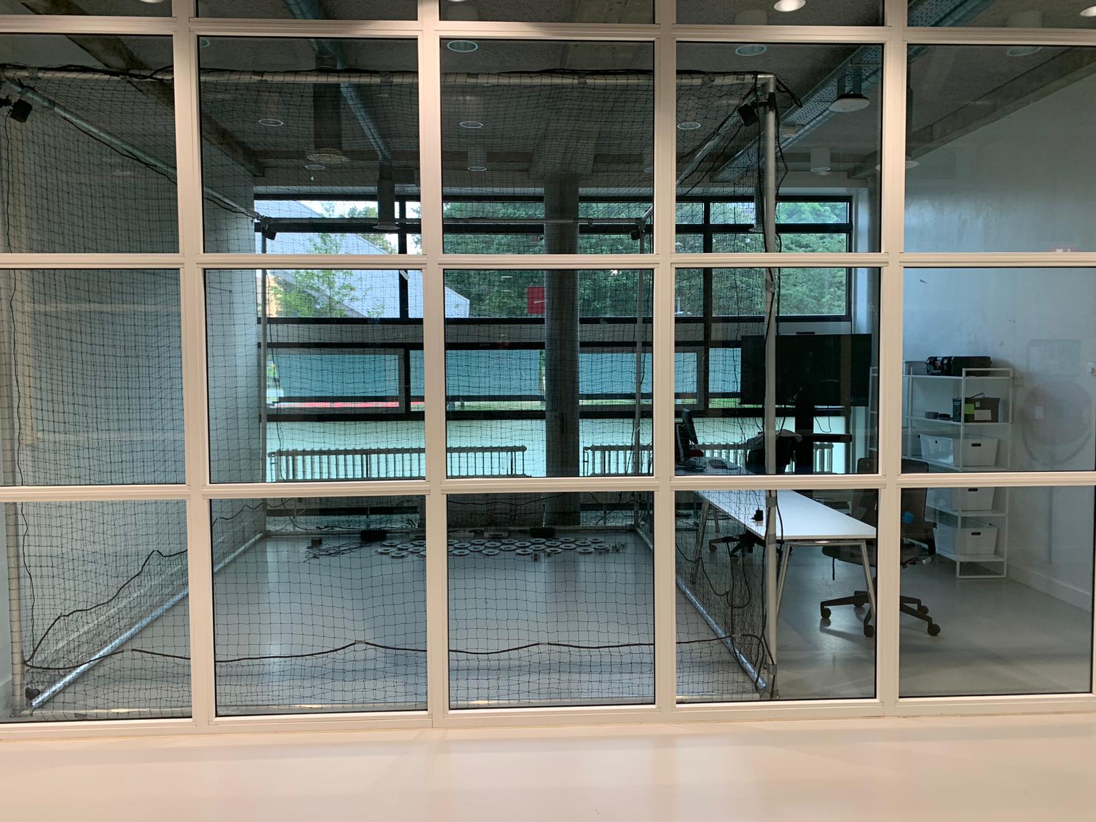
The next step in this project will be to set up the swarm at its new location, the TU Delft Science Centre. Here, the swarm will first and foremost be visible as a public demo, showcasing the capabilities of TU Delft state-of-the-art swarming research. There will also be a focus on developing the swarm as a research platform. This will allow TU Delft students and researchers to extend swarm functionalities and test their theory on a physical swarming system. Besides demos and academic research, there will also be worked on developing educational applications across the full educational board (primary school, high school and applied education). If you are interested in working on, or collaborating with the swarming lab on any of the above-mentioned tasks, feel free to email the lab management at operations.swarminglab@tudelft.nl.
The TU Delft Swarming Lab setup with 40 drones and charging pads for continuous operations and research.
Applications of Swarming
There are a lot of potential use-cases for fully autonomous drone swarms, ranging from indoor applications such as warehouse monitoring and factory inspection to outdoor applications such as search and rescue and surveillance. In our opinion, the true potential of drone swarms lies in applications where there is a significant need for a scalable system with a lot of built-in redundancy. A lot of additional use cases open up when we consider fully onboard autonomous systems, where the full benefits of decentralized swarming can be utilized. Currently, the size of drones needed to achieve such feats is quite large, though maybe in a few years, we could see more and more being done on drone platforms such as the Crazyflie.
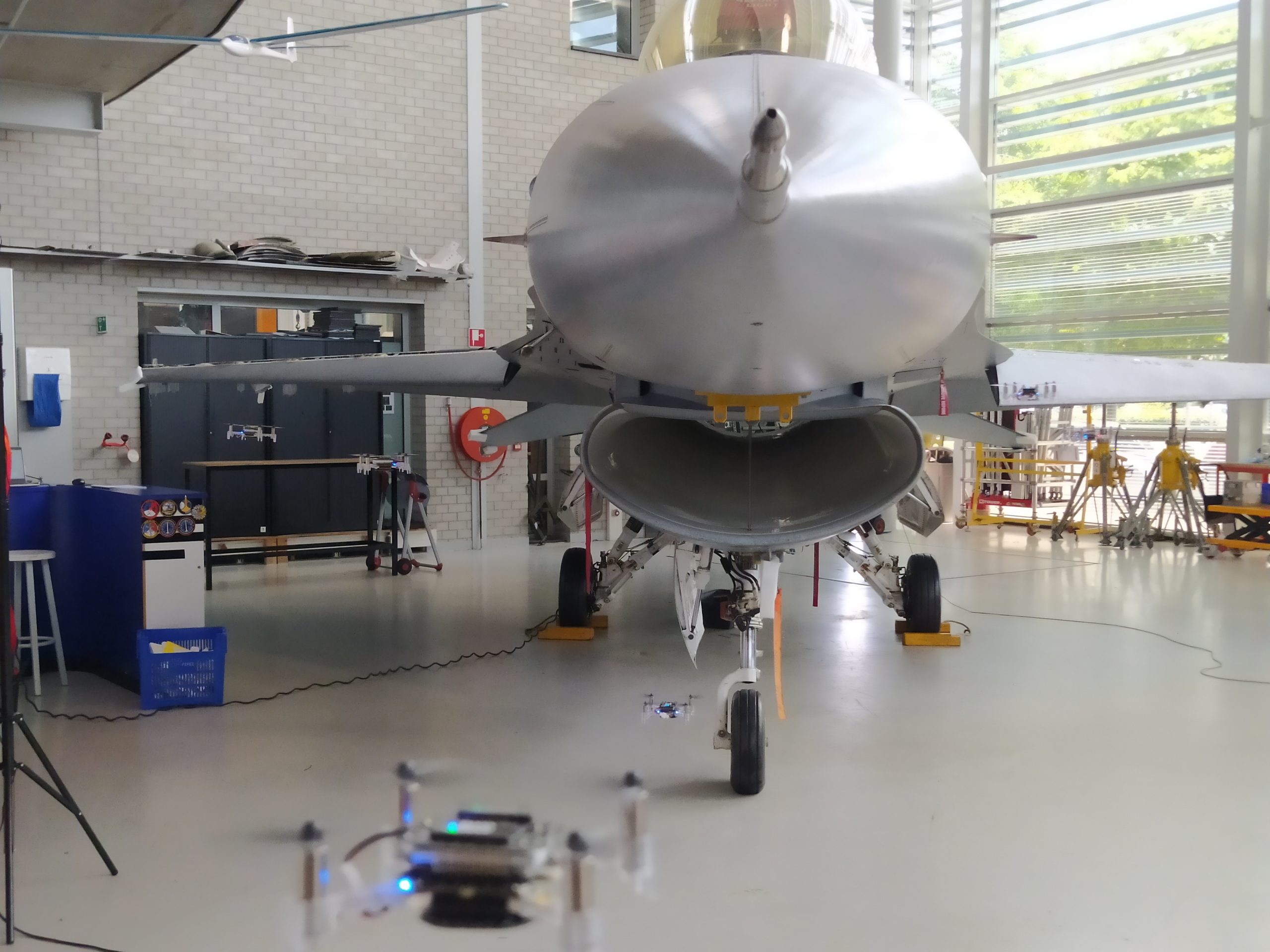
A swarm inspection of an F-16 Fighting Falcon at Deltion College in Zwolle, the Netherlands.
An interesting area of application for drone swarms could be in the inspection of aircraft. Drone swarms provide a scalable and flexible means to perform a fast inspection of aircraft across an entire airfield or military base. To showcase that this can be done with any size of drone, we went to Deltion College in Zwolle to perform a mock inspection of an F-16 fighter jet. Above you can see an impression of the inspection. Another area of application is search and rescue, where there is a need for systems that can find people or objects of interest in unknown and cluttered environments. Furthermore, the area that needs to be searched is usually very large and sometimes difficult to travel on foot. A drone swarm could provide fast and reliable coverage of the area of interest, whilst providing full data traceability. Seppe and Lennart will work on creating drone swarms for these use cases with the start-up Emergent Swarms.
In our ROS-aerial community working group, we had a meeting a few weeks ago to discuss education and tutorials within Aerial Robotics (see the ROS discourse thread here). The general conclusion was that there should be more courses and tutorials since the learning curve is too steep. But… is that actually the case? According to a LinkedIn post by Kimberly, asking for suggestions, we found out that might not be true! There are loads of tutorials out there! So in this blog post, we will provide an overview of the suggested tutorials and the ones that have materials available online.
Stable diffusion with prompt ‘A drone flying in front of a school blackboard’
Online books
One of the first suggestions was to explore the online free book titled ‘Small Unmanned Aircraft: Theory and Practice.’ This book has been written by Randy Beard and Tim McLain of Brigham Young University, and it covers everything from the absolute basics of coordinate frames and quadrotor dynamics to path planning and cameras. It is a must-read for anybody starting in UAVs and Aerial robotics.
Here are some suggestions for courses specifically focused on Aerial Robotics. These received the most recommendations! Many universities have made their courses available online, accessible to anyone interested.
Coursera offers the ‘Robotics: Aerial Robotics’ course as part of the Robotics specialization. Taught by Prof. Vijay Kumar from Penn University, this 4-week course covers the mechanics and control of aerial vehicles using Matlab. It starts from 1 dimension and gradually progresses to the 3rd dimension in simulation. The course is part of a paid educational program, but you can audit the lessons for free.
Udacity has been offering a course on Aerial Vehicles for quite some time. The lessons are taught by top names in the industry and cover key aspects of Aerial Robotics, such as motion planning, controls, and estimation, with lab assignments involving a real drone. The course duration is 4 months, and access is available for a fee.
The University of Maryland offers a course on Autonomous Aerial Robotics, making all videos, slides, and assignments available. Taught by Nitin J. Sanket and Chahat Deep Singh, the course covers everything from basic control and dynamics to full autonomy. It’s a comprehensive resource for aerial robotics. The course utilizes the Parrot Bebop 2.0, and while a Mocap system is required, you may explore the possibility of adapting the course to a different platform.
Additionally, there’s the course ‘Applied Control System 3: UAV Drone (3D Dynamics & Control)’ which is part of a series by Mark Misin. This course delves deep into the dynamics, control, and modeling of quadrotors.
Here are some suggestions for courses that focus on robotics but utilize UAVs/drones to demonstrate the implementation of the studied materials.
‘Visual Navigation For Autonomous Vehicles’ is a course available on MIT Open Courseware, taught by Prof. Luca Carlone. As the name implies, the course primarily focuses on autonomous navigation for any autonomous vehicle. It includes exercises where students implement vision algorithms on both ground robots and drones. Additionally, the course covers working with ROS and applying the knowledge to a simulated drone in Unity.
The ‘Bio-inspired Robotics’ course at the University of Washington, led by Prof. Sawyer Fuller, explores the realm of drawing inspiration from nature rather than reinventing the wheel. It covers various robots inspired by creatures capable of swimming, walking, hopping, and of course, flying. Lab assignments in this course involve working with a Crazyflie drone.
Brown University offers a course called ‘Introduction to Robotics,’ taught by Prof. Stefanie Tellix. While the introduction covers generic robotics, the focus of the full course is on building and programming the Duckiedrone. The course dives straight into autonomy and also teaches students how to work with ROS.
Princeton University (see this blogpost) have also decided to release their ‘Intro to Robotics’ lectures and materials for the public. Can’t believe I forgot this one!
If you’d like to start hands-on right away, here are a couple of suggestions for YouTube tutorials or series about aerial robotics.
Drone Programming with Python: This popular tutorial/course teaches viewers how to program a real drone using Python with the DJI Tello. It offers a great opportunity for anyone looking for a short and enjoyable project to undertake, especially on a rainy day, while still working with a real platform.
Intelligent Quads YouTube Channel: This channel is entirely dedicated to creating autonomous UAVs, covering topics from Ardupilot to MAVlink to ROS and Gazebo. It appears to be a valuable resource for beginners in the field of autonomous UAVs.
There are some extra recourses for you to also take a look at.
University of Twente UAV Centre: The University of Twente has created a portal with a variety of UAV-related courses. You can find a wealth of information and educational materials on their website. Link: https://www.itc.nl/facilities/centres-of-expertise/uav-centre/
Self-Driving Car Specialization: If you are interested in learning more about SLAM (Simultaneous Localization and Mapping) and sensors, this specialization is tailored for self-driving cars but the theory can be useful for drones as well. Link: https://www.coursera.org/specializations/self-driving-cars
Autonomous Navigation for Flying Robots: This older course is still highly relevant for anyone interested in autonomous navigation for flying robots. It offers valuable insights and knowledge. Link: https://www.edx.org/course/autonomous-navigation-for-flying-robots
Drone Dojo: For those looking to build their own drones, Drone Dojo provides useful instructions and courses to get started on DIY drone projects. Link: https://dojofordrones.com/
Indeed, it appears that there are plenty of courses and tutorials available for people interested in getting started with aerial robotics. The range of resources is vast, and it’s possible that we might still be missing some, which could lead to a part 2 of this blog post in the future! And perhaps also we would need to delve into these to see why the learning curve is considered steep. However, aerial robotics is not an easy subject anyway so perhaps it is good to start from the basics. Nevertheless, this compilation should provide a solid starting point for anyone eager to delve into the world of aerial robotics. A major thank you to everyone who has contributed so far (linked to in the original LinkedIn post); your valuable input has made this possible!