As you probably noticed already, this summer I experimented with ROS2 and connecting the Crazyflie with multi-ranger to several mapping and navigation nodes (see this and this blogpost). First I started with an experimental repo on my personal Github account called crazyflie_ros2_experimental, where I managed to do some mapping and navigation already. In August we started porting most of this functionality to the crazyswarm2 project, so that is what this blogpost is mostly about.
Crazyswarm goes ROS2
Most of you are already familiar with Crazyswarm for ROS1, which is a project that Wolfgang Hönig and James Preiss have maintained since its creation in 2017 at the University of Southern California. Since then, many have used and referred to this work, since the paper has been cited more than 260 times. From all the Crazyflie papers of the latest ICRA and IROS conferences, 50 % of the papers have used Crazyswarm as their communication middleware. If you haven’t heard about Crazyswarm yet, please check-out the nice BAMdays talk Wolfgang gave last year.
Unfortunately, ROS1 will not be there forever and will be phased out anno 2025 and will not be supported for Ubuntu 22.04 and up. Therefore, Wolfgang, now at the Intelligent Multi-robot Coordination Lab at TU Berlin, has already started with the ROS2 port of Crazyswarm, namely Crazyswarm2. Here the same principle of the C++ based Crazyflie server and the python wrapper were been implemented, along with the simple position based simulation and Teleop nodes. Mind that the name Crazyswarm2 is just the project name out of historic reasons, but the package itself can also be used for individual Crazyflies as well. That is why the package names will be called crazyflie_*
Porting the Summer Hack project to Crazyswarm2
The crazyflie_ros2_experimental was fun to hack around, as it was (as the name suggests) experimental and I didn’t need to worry about releases, bugfixes etc. However, the problem of developing only here, is that the further you go the more work it becomes to make it more official. That is when Wolfgang and I sat down and started talking about porting what I’ve done in the summer into Crazyswarm2. This is also a good opportunity to get more involved with the project, especially with so many Crazyfliers using the ROS as well.
The first step was to write a second crazyflie_server node that relied on the python CFlib. This means that many of the variables I used to hardcode in the experimental node, needed to be defined within the parameter structure of ROS2. The crazyflies.yaml is where anything relevant for the server (like the URIs and parameters) needs to be defined. Both the C++ backend server and the CFlib backend server are using the same parameters. Also the functionality of the both servers are pretty similar, except for that logging is only possible on the CFlib version and uploading/follow trajectories is only possible on the C++ version. An overview will be provided soon on the Crazyswarm2 documentation website.
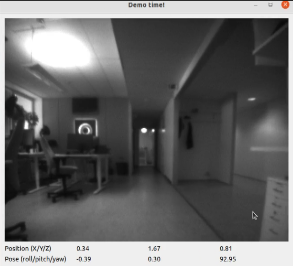
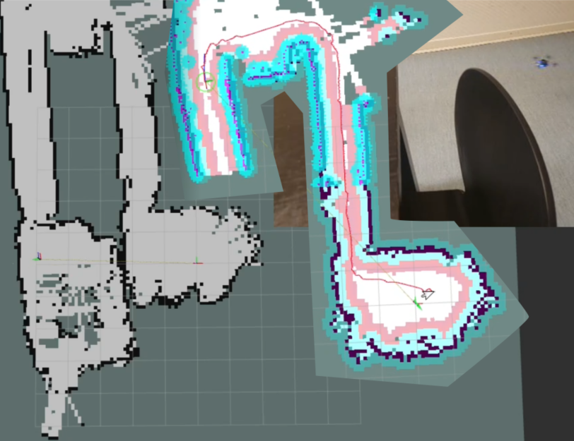
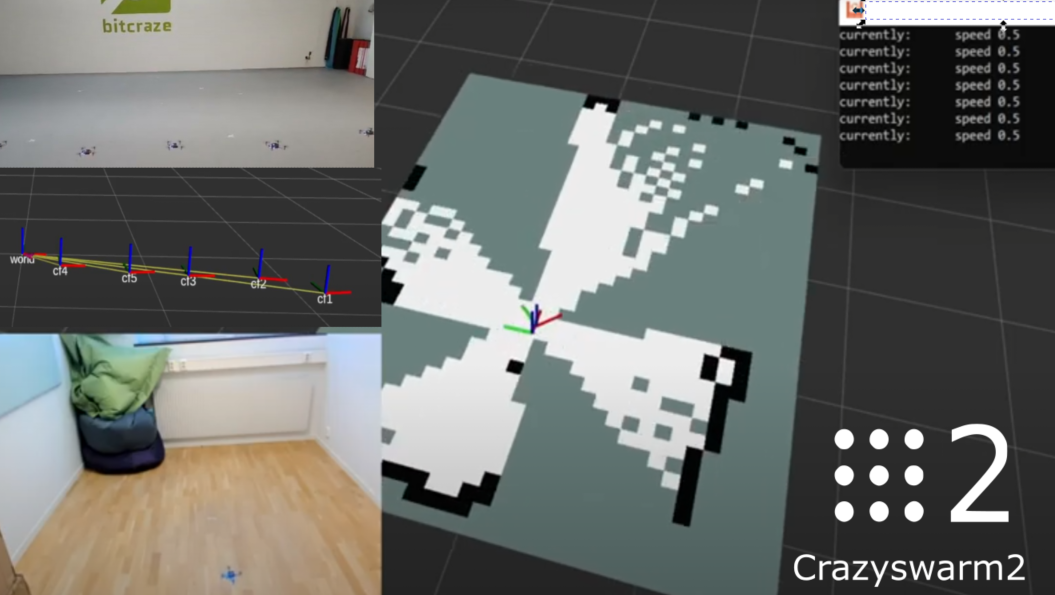
The second step was to make the crazyflie_server (cflib) node suitable to be connected to external packages that I’ve worked with during the hack project. Therefore, there are some special logging modes, that enables the server to not only output topics based on logging, but Pose/Odometry/LaserScan messages along with Transforms. This allowed the SLAM_toolbox to use the data from the Crazyflie itself to create a map, which you can see an example of in this tutorial.
Moreover, for the navigation it was important that incoming Twist messages either from keyboard or from a navigation toolkit were handled properly. Most of these packages assume a 2D non-holonomic robot, but a quadcopter like the Crazyflie needs to first take off, stay in the air and land. Therefore in the examples, a separate node (vel_mux.py) was written to receive incoming Twist messages, first have the Crazyflie take off in high level commander, and keep sending hover commands to keep it in the air until a land service is called.
What’s next?
As you probably noticed, the project is still under development, but at least it is now at a good state that we feel comfortable to presented at the upcoming ROScon :) We also want to include an more official simulation package, especially now that the Crazyflie has recently became part of the official release of Webots 2022b, but we are currently waiting on the webots_ros2 to be released in the ubuntu packages. Moreover, the idea is to provide multiple simulation backends that based on the requirement of the topic (swarms, vision-based etc), the user can select the simulation most useful for their situation. Also, we would like to even out the missing items (trajectory handling, logging) in both the cflib and cpp backend of the crazyflie_server so that they can be used interchangeably. Also, I saw that the experimental simple mapper node has been featured on social media, so perhaps we should be converting that to Crazyswarm2 as well :)
So once we got the most of the above mentioned issues out the way, that will be the time that we can start discussing the official release of a ROS2 Crazyflie package with its source code residing in the Crazyswarm2 repository. In the meantime, it would be awesome that anybody that is interested in ROS2, or want to soon upgrade their Crazyswarm(1) packages to ROS2 to give the package a whirl. The more people that are trying it out and report bugs/proposing fixes, the more stable it becomes and closer it will come to an official release! Please join us and start any discussions on the Crazyswarm2 project github repository.
- Crazyswarm2 documentation: https://imrclab.github.io/crazyswarm2/
- Crazyswarm2 source code: https://github.com/IMRCLab/crazyswarm2
- ROScon 2022 talk: ROS 2 and the Crazyflie: Aerial swarms and Autonomy with a tiny flying robot