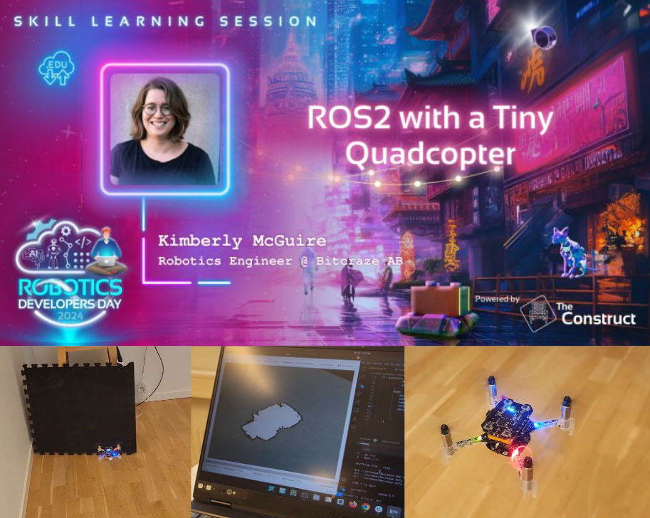
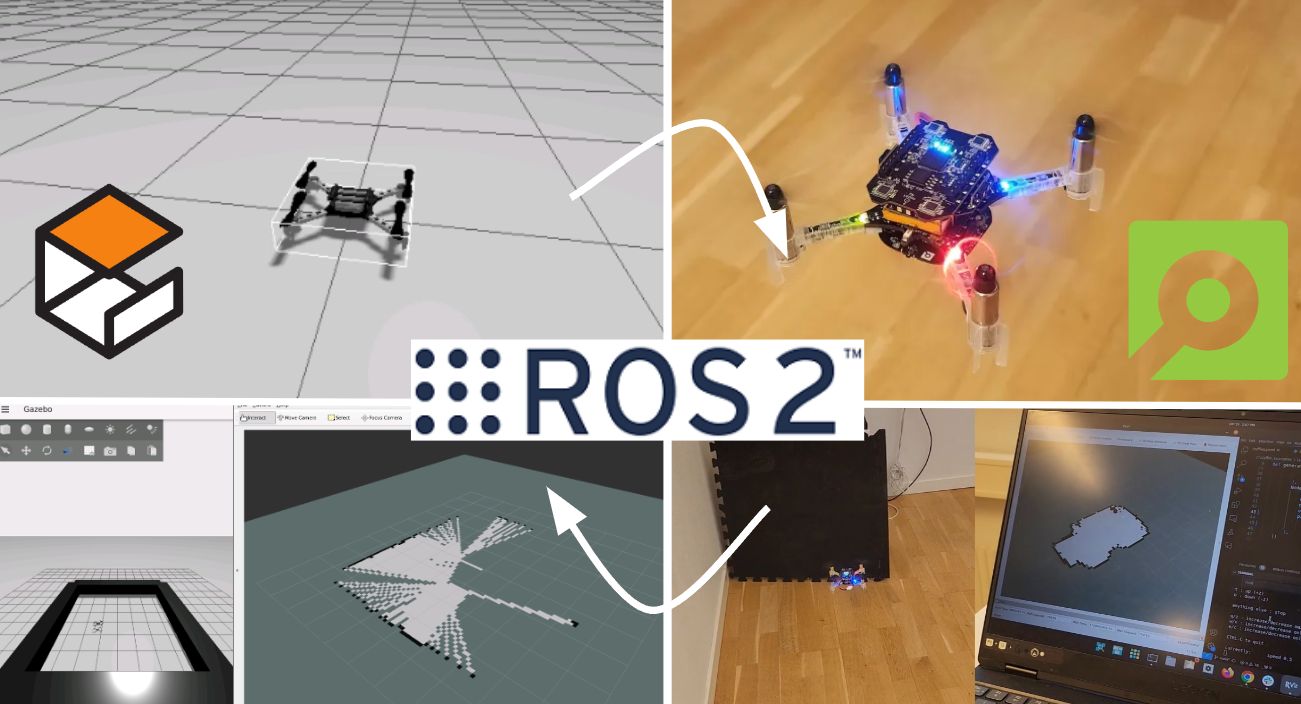
You might remember that at the beginning of this summer, we were invited to do a skill-learning session with the Crazyflie at the Robotics Developer Day 2024 (see this blog post) organized by The Construct. We showed the Crazyflie flying with the multi-ranger deck, capable of mapping the room in both simulation and the real world. Moreover, we demonstrated this with both manual control and autonomous wall-following. Since then, we wanted to make some improvements to the simulation. We now present an updated tutorial on how to do all of this yourself on your own machine.
Note: This tutorial was originally developed for a demonstration at Robotics Developer Day 2024. As the integration depends on specific versions of ROS 2, Gazebo, and related packages, it may require adjustments to work with current software. This post is no longer actively maintained by the Bitcraze team.
This tutorial will focus on using the multi-ranger ROS 2 nodes for both mapping and wall-following in simulation first, before trying it out on the real thing. You will be able to tune settings to your specific environment in simulation first and then use exactly the same nodes in the real world. That is one of the main strengths of ROS, providing you with that flexibility.
We have made a video of what to expect of the tutorial, for which you should use this blogpost for the more detailed instructions.
What do you need first?
You’ll need to setup some things first on the PC and acquire hardware to follow this tutorial in full:
PC preparation
You’ll need to install ROS 2 and Gazebo simulator maintained by the Open Robotics foundation on an Ubuntu machine.
- Ubuntu 22.04 on a 64-bit x86 device (no ARM)
- ROS 2 Humble – Install it via these instructions
- Gazebo Harmonic – Install via these instructions This is not the recommended Gazebo for humble but we will install the specific ROS bridge for this later. Just make sure that you don’t have gazebo classic installed on your machine.
Hardware
You’ll need to components at least of the STEM ranging bundle
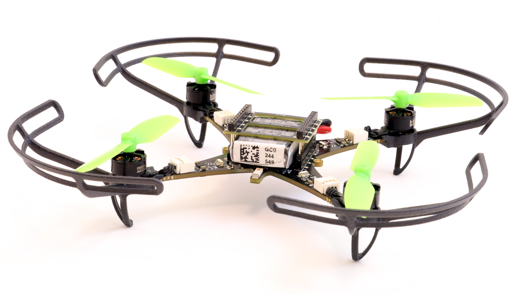
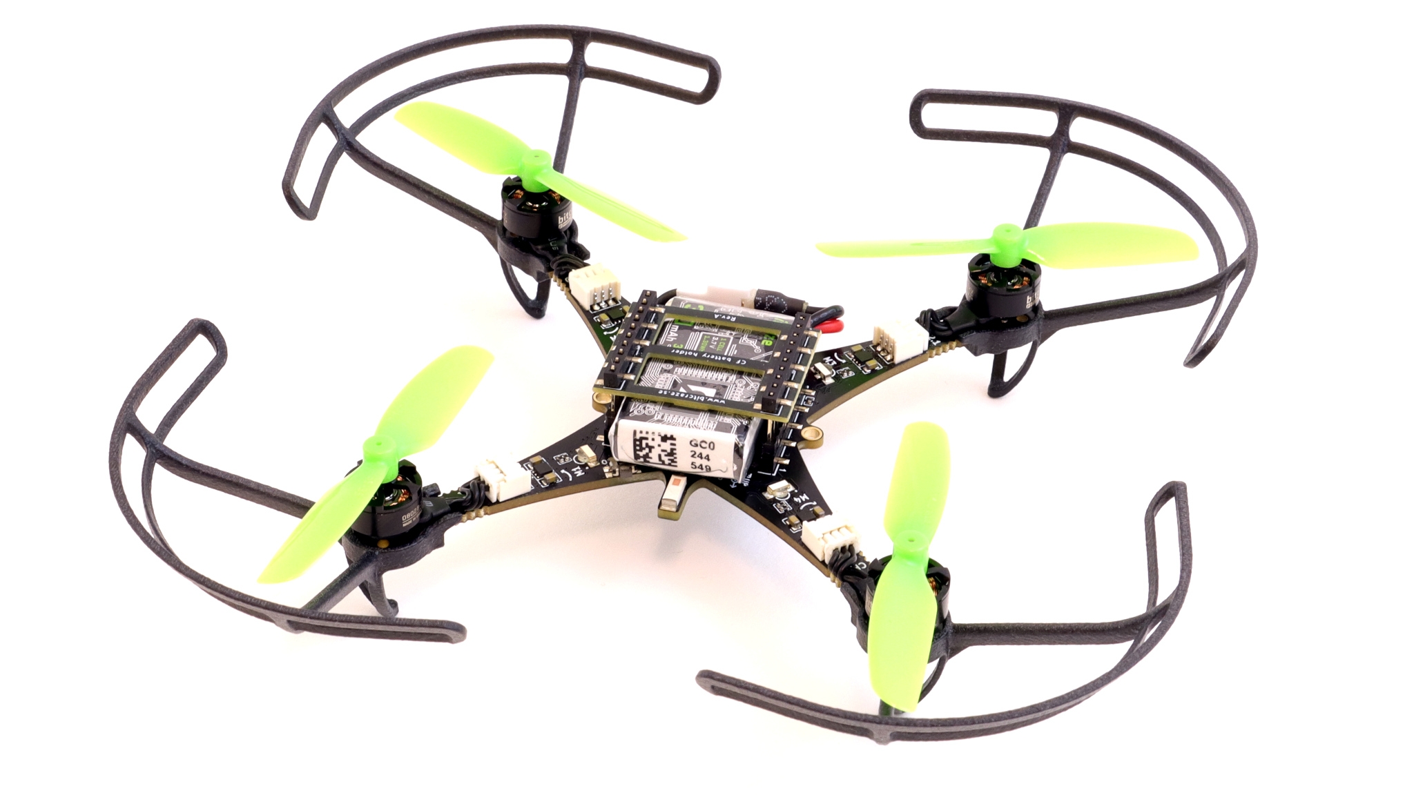
- Crazyflie 2.1+
- Multi-ranger deck
- Flow deck v2 (see this blogpost for tips and tricks)
- Crazyradio 2.0
If you have any different setup of your computer or positioning system, it is okay as the demos should be simple enough to work, but, be prepared for some warning/error handling that this tutorial might have not covered.
Time to complete:
This is an approximation of how much time you need to complete this tutorial, depended on your skill level, but if you already have experience with both ROS 2/Gazebo and the Crazyflie it should take 1 hour.
If you have the Crazyflie for the first time, it would probably be a good idea to go through the getting started tutorial and connect to it with a CFclient with the Flowdeck and Multi-ranger deck attached as a sanity check if everything is working before jumping into ROS 2 and Gazebo.
Some things holds for ROS 2! It would be handy to go through the ROS 2 Humble beginner tutorials before starting.
1. Installation
This section will install 4 packages:
- crazyflie_simulation: Contains the gazebo model for the Crazyflie with a lidar as multiranger
- crazyswarm2: This provides the communication link and ROS2 intergration with the Crazyflie
- ros_gz_crazyflie: This handles the bridging between Gazebo and ROS 2
- crazyflie_ros2_multiranger: This handles the simple mapping and wall following autonomy nodes.
Make the workspaces for both simulation and ROS. You can use a different directory for this
mkdir ~/crazyflie_mapping_demo
cd crazyflie_mapping_demo
mkdir simulation_ws
mkdir ros2_ws
cd ros2_ws
mkdir src
Let’s clone the repositories in their right location, starting with simulation
cd ~/crazyflie_mapping_demo/simulation_ws
git clone https://github.com/bitcraze/crazyflie-simulation.gitCode language: JavaScript (javascript)
Then navigate to the ROS2 workspace source folder and clone 3 projects:
cd ~/crazyflie_mapping_demo/ros2_ws/src
git clone https://github.com/knmcguire/crazyflie_ros2_multiranger.git
git clone https://github.com/knmcguire/ros_gz_crazyflie
git clone https://github.com/IMRCLab/crazyswarm2 --recursiveCode language: PHP (php)
First install certain requirements as apt-get packages and pip libraries (might want to make a python environment for the latter)
sudo apt-get install libboost-program-options-dev libusb-1.0-0-dev python3-colcon-common-extensions
sudo apt-get install ros-humble-motion-capture-tracking ros-humble-tf-transformations
sudo apt-get install ros-humble-ros-gzharmonic ros-humble-teleop-twist-keyboard
pip3 install cflib transform3D Code language: JavaScript (javascript)
Also follow the instructions to give the proper rights to the Crazyradio 2.0 in this guide, but if this is your first time of working with the Crazyradio 2.0 first follow this tutorial.
Go to the ros2_ws workspace and build the packages
cd  ~/crazyflie_mapping_demo/ros2_ws/
source /opt/ros/humble/setup.bash
colcon build --cmake-args -DBUILD_TESTING=ONCode language: JavaScript (javascript)
Building will take a few minutes. Especially Crazyswarm2 will show a lot of warnings and std_err, but unless the package build has ‘failed’, just ignore it for now until we have proposed a fix to that repository.
If the build of all the packages passes and non failed, please continue to the next step!
2. Simple mapping simulation
This section will explain how to create a simple 2D map of your environment using the multi-ranger. The ROS 2 package designed for this is specifically made for the multi-ranger, but it should be compatible with NAV2 if you’d like. However, for now, we’ll focus on a simple version without any localization inferred from the map.
Open up a terminal which needs to be sourced for both the gazebo model and the newly build ROS 2 packages:
source ~/crazyflie_mapping_demo/ros2_ws/install/setup.bash
export GZ_SIM_RESOURCE_PATH="/home/$USER/crazyflie_mapping_demo/simulation_ws/crazyflie-simulation/simulator_files/gazebo/"Code language: JavaScript (javascript)
First lets be safe and start with simulation. Startup the ROS 2 launch files with:
ros2 launch crazyflie_ros2_multiranger_bringup simple_mapper_simulation.launch.pyCode language: CSS (css)If you get a ‘No such file or directory’ error on the model, try entering the full path in GZ_SIM_RESOURCE_PATH export.
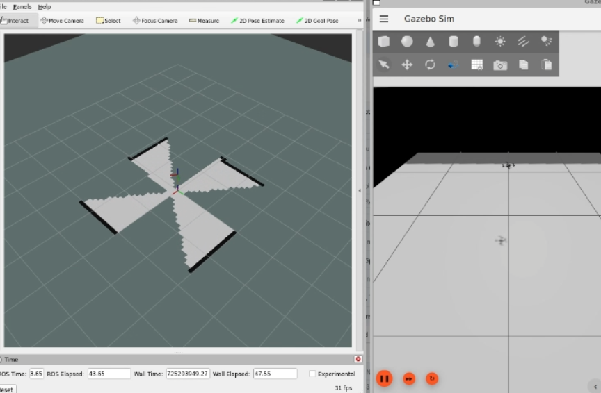
Gazebo will start with the Crazyflie in the center. You can get a close-up of the Crazyflie by right-clicking it in the Entity tree and pressing ‘Move to’. You can also choose to follow it, but the camera tracking feature of Gazebo needs some tuning to track something as small as the Crazyflie. Additionally, you will see RVIZ starting with the map view and transforms preconfigured.
Open up another terminal, source the installed ROS 2 distro and open up the ROS 2 teleop keyboard node:
source /opt/ros/humble/setup.bash
ros2 run teleop_twist_keyboard teleop_twist_keyboard
Have the Crazyflie take off with ‘t’ on your keyboard, and rotate it around with the teleop instructions. In RVIZ you should see the map being created and the transform of the Crazyflie moving. You should be able to see this picture, and in this part of the video.
3. Simple mapping real world
Now that you got the gist of it, let’s move to the real Crazyflie!
First, if you have a different URI of the Crazyflie to connect to, first change the config file ‘crazyflie_real_crazyswarm2.yaml’ in the crazyflie_ros2_repository. This is a file that Crazyswarm2 uses to know to which Crazyflie to connect to.
Open up the config file in gedit or your favorite IDE like visual code:
gedit ~/crazyflie_mapping_demo/ros2_ws/src/crazyflie_ros2_multiranger/crazyflie_ros2_multiranger_bringup/config/crazyflie_real_crazyswarm2.yamlCode language: JavaScript (javascript)and change the URI on this line specifically to the URI of your Crazyflie if necessary. Mind that you need to rebuild ros2_ws again to make sure that this has an effect.
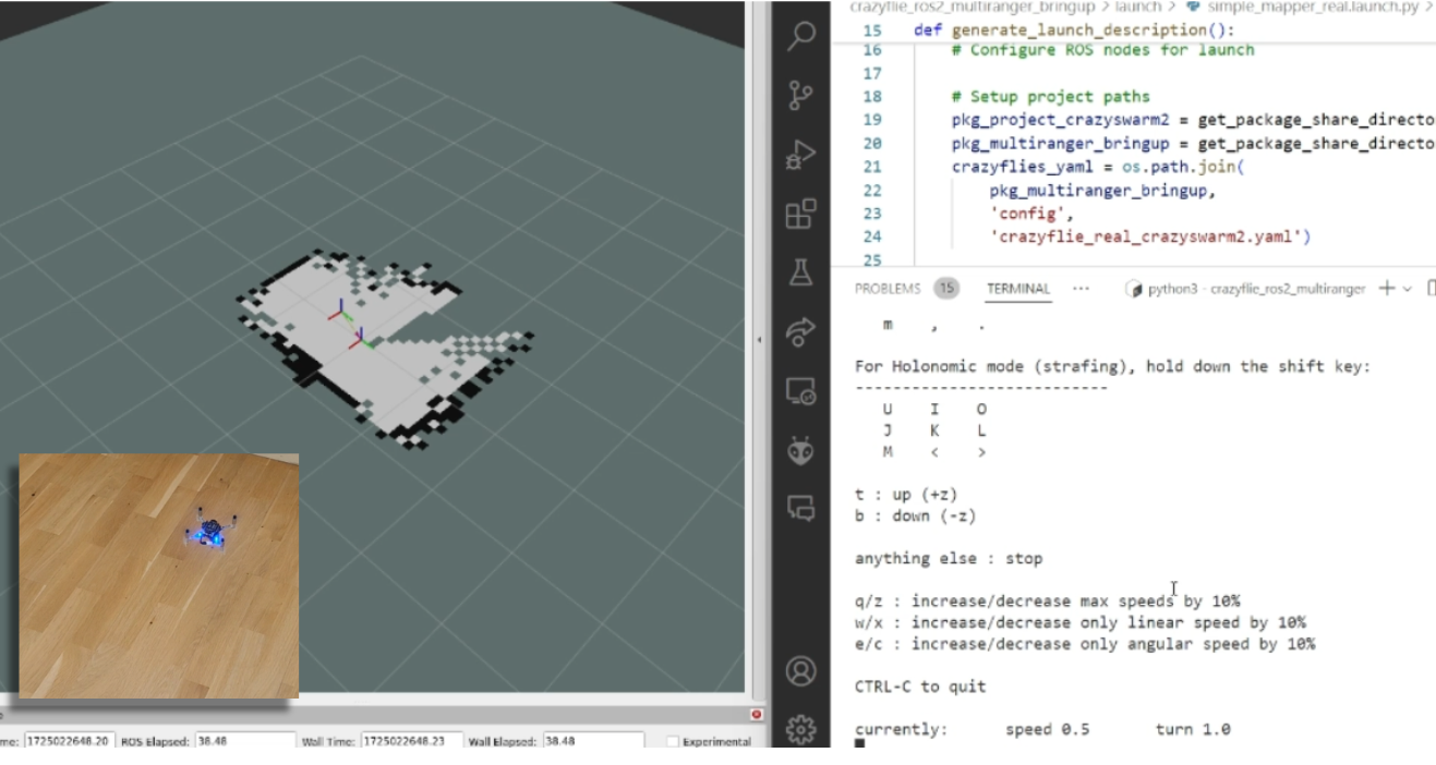
Now source the terminal with the installed ROS 2 packages and the Gazebo model, and launch the ROS launch of the simple mapper example for the real world Crazyflie.
source ~/crazyflie_mapping_demo/ros2_ws/install/setup.bash
export GZ_SIM_RESOURCE_PATH="/home/$USER/crazyflie_mapping_demo/simulation_ws/crazyflie-simulation/simulator_files/gazebo/"
ros2 launch crazyflie_ros2_multiranger_bringup simple_mapper_real.launch.py
Code language: JavaScript (javascript)
Now open up another terminal, source ROS 2 and open up teleop:
source /opt/ros/humble/setup.bash
ros2 run teleop_twist_keyboard teleop_twist_keyboard
Same thing, have the Crazyflie take off with ‘t’, and control it with the instructions.
You should be able to see this on your screen, which you can also check with this part of the video.
Make the Crazyflie land again with ‘b’, and now you can close the ROS 2 node in the launch terminal with ctrl + c.
4. Wall following simulation
Previously, you needed to control the Crazyflie yourself to create the map, but what if you could let the Crazyflie do it on its own? The `crazyflie_ros2_multiranger` package includes a `crazyflie_ros2_multiranger_wall_following` node that uses laser ranges from the multi-ranger to perform autonomous wall-following. Then, you can just sit back and relax while the map is created for you!
Let’s first try it in simulation, so open up a terminal and source it if you haven’t already (see section of the Simple mapper simulation). Then launch the wall follower ROS 2 launch file:
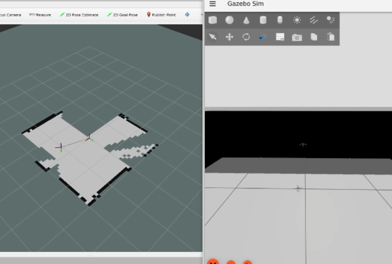
ros2 launch crazyflie_ros2_multiranger_bringup wall_follower_mapper_simulation.launch.pyCode language: CSS (css)Take off and wall following will go fully automatic. The simulated Crazyflie in Gazebo will fly forward, stop when it sees a wall with it’s forward range sensor and follow the wall on its left-hand side.
You’ll see on RVIZ2 when the full map is created like here below and this part of the tutorial video.
You can stop the simulated Crazyflie by the following service call in another terminal that is sourced with ROS 2 humble.
ros2 service call /crazyflie/stop_wall_following std_srvs/srv/TriggerThe simulated Crazyflie will stop wall following and land. You can also just close the simulation, since nothing can happen here.
5. Wall following real world
Now that we have demonstrated that the wall-following works in simulation, we feel confident enough to try it in the real world this time! Make sure you have a fully charged battery, place the Crazyflie on the floor facing the direction you’d like the positive x-axis to be (which is also where it will fly first), and turn it on.
Make sure that you are flying with a room with clear defined walls and corners, or make something with cardboard such as a mini maze, but the current algorithm is optimized to just fly in a squarish room.
Source the ROS 2 workspace like previously and start up the wall follower launch file for the
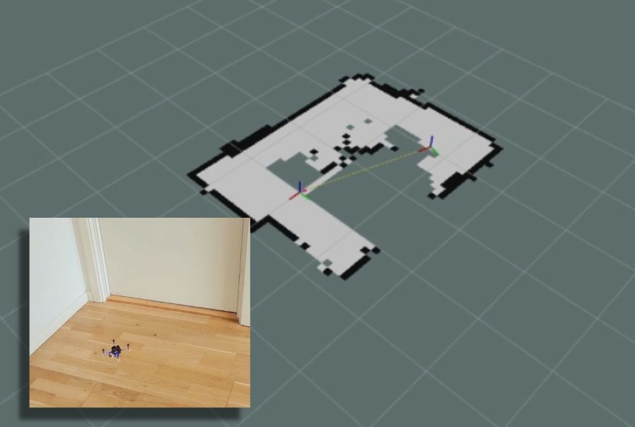
ros2 launch crazyflie_ros2_multiranger_bringup wall_follower_mapper_real.launch.pyCode language: CSS (css)Like the simulated Crazyflie, the real Crazyflie will take off automatically and automatically do wall following, so it is important that it is flying towards a wall. It should look like this screenshot, or you can check it with this part of the video.
Be careful here to not accidently run this script with the Crazyflie sitting on your desk!
If you’d like the Crazyflie to stop, don’t stop the ROS2 nodes with ctrl-c, since it will continue flying until crash. It’s not like simulation unfortunately where you can close the environment and nothing will happen. Instead, use the ROS 2 service made for this in a different terminal:
ros2 service call /crazyflie_real/stop_wall_following std_srvs/srv/TriggerSimilar the real Crazyflie will stop wall following and land. Now you can close the ROS 2 terminals and turn off the crazyflie.
Next steps?
We don’t have any more demos to show but we can give you a list of suggestions of what you could try next! You could for instance have multiple Crazyflies mapping together like in the video shown here:
This uses the mapMergeForMultiRobotMapping-ROS2 external project, which is combined with Crazyswarm2 with this launch file gist. Just keep in mind that, currently, it would be better to use a global positioning system here, such as the Lighthouse positioning system used in the video. Also, if you’d like to try this out in simulation, you’ll need to ensure different namespaces for the Crazyflies, which the current simulation setup may not fully support.
Another idea is to connect the NAV2 stack instead of the simple mapper. There exists a couple of instructions on the Crazyswarm2 ROS2 tutorials so you can use those as reference. Check out the video below here.
Moreover, if you are having difficulties setting up your computer, I’d like to remind you that the skill-learning session we conducted for Robotics Developer Day was entirely done using a ROSject provided by The Construct, which also allows direct connection with the Crazyflie. The only requirement is that you can run Crazyswarm2 on your local machine, but that should be feasible. See the video of the original Robotics Developer Day skill-learning session here:
The last thing to know is that the ROS 2 nodes in this tutorial are running ‘offboard,’ so not on the Crazyflies themselves. However, do check out the Micro-ROS examples for the Crazyflie by Eprosima whenever you have the time and would like to challenge yourself with embedded development.
Happy hacking!